Underwater connection installation

US8418766B2Active Publication Date: 2013-04-16TECH FRANCE SA

Image

  • Underwater connection installation
  • Underwater connection installation
  • Underwater connection installation

Examples


Embodiment Construction

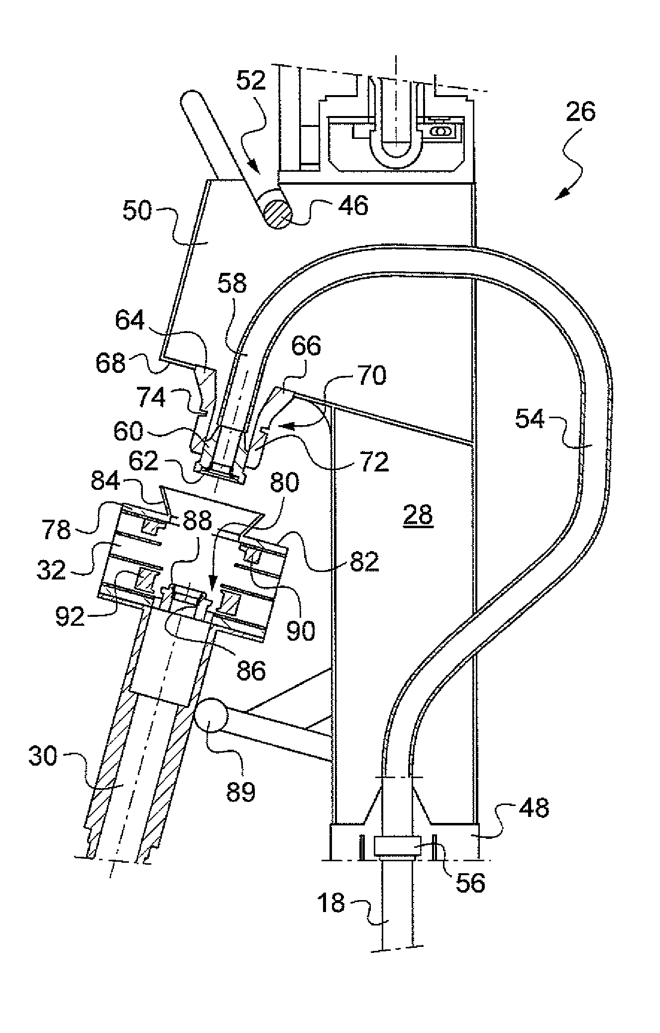
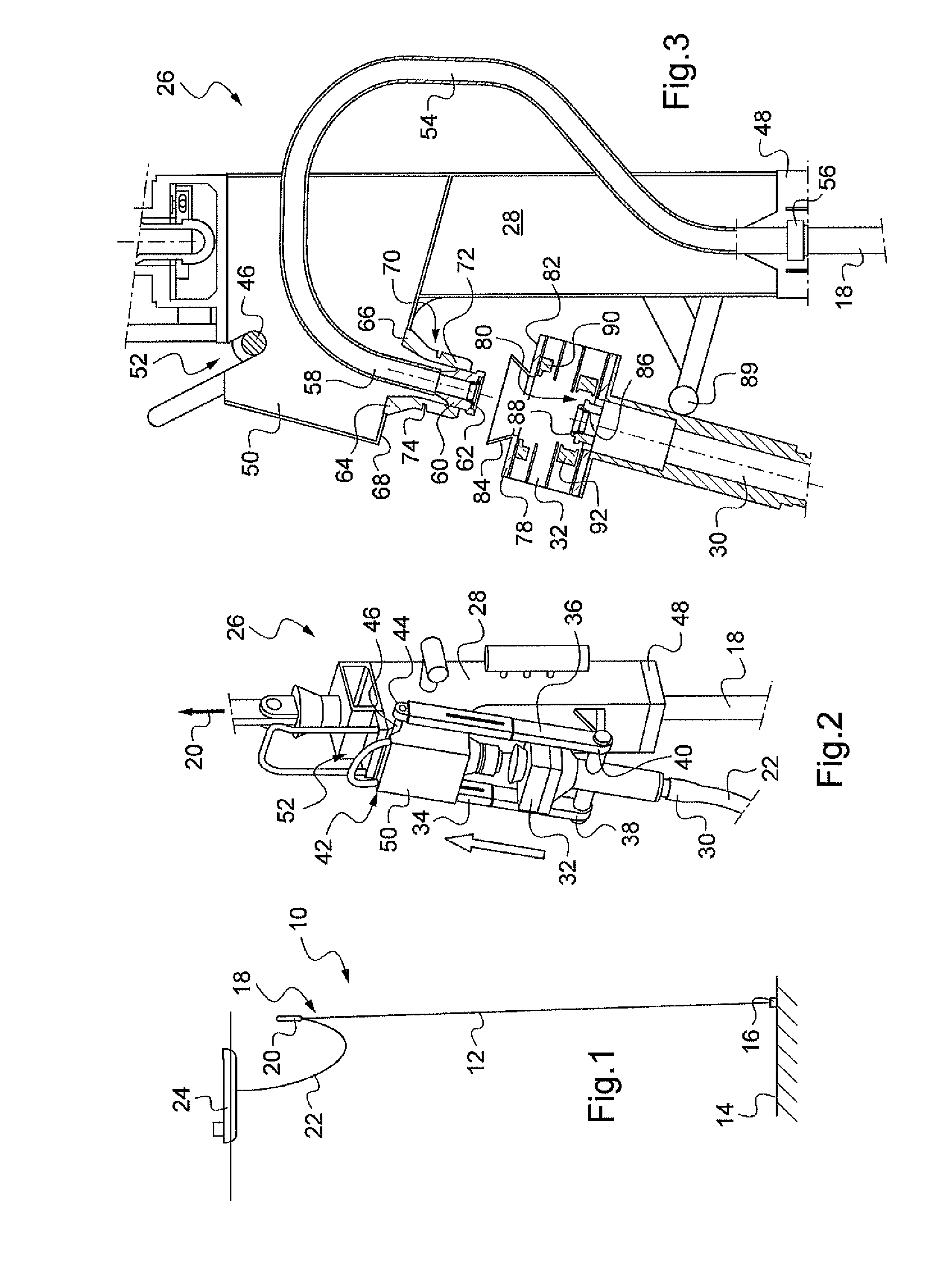
[0029]FIG. 1 shows schematically a hybrid tower 10 comprising a rigid riser 12 attached to a seabed 14 by means of an anchoring system 16. Moreover, the rigid riser 12 has a top portion 18, or top end, suspended from a float 20, or a buoy, in which a sufficient quantity of air is trapped to keep the rigid riser in its vertical position. Moreover, the hybrid tower 10 comprises a flexible pipe 22 which extends in catenary suspension between a surface ship 24 and the top end 18 of the rigid riser 12. Therefore, an underwater connection installation 26 according to the invention shown in detail in FIG. 2 and forming a connector, makes it possible to connect together the riser 12 and the flexible pipe 22 in catenary suspension. Reference will be made to FIG. 2 to describe first detail elements of the connection installation 26.

[0030]The connection installation 26 therefore comprises a post 28 which forms a connection assembly and which is placed between the float 20 and the rigid riser 1...


PUM


Abstract

An underwater connection installation (26) and a laying method for connecting a riser and a flexible pipe (22) that are intended for carrying hydrocarbons. A post (28) is attached to a float (20) to suspend the riser (12) below the surface. The post (28) supports a gooseneck shape pipe (54) that has a bent-over outlet free end (58) ending in a first coupling (60). A coupling end piece (32) mounted on the flexible pipe (22) includes a second coupling (86). The coupling end piece (32) and the post (28) define mechanical guides including complementary frustoconical rings (64, 84). The driving of the coupling end piece (32) and of the bent-over free end (58) toward each other causes the frustoconical rings (64, 84) to engage one another to bring about coaxial alignment of the couplings (60, 86).

Description

CROSS REFERENCE TO RELATED APPLICATION[0001]The present application is a 35 U.S.C. §§371 national phase conversion of PCT / FR2009 / 000075 filed Jan. 23, 2009, which claims priority of French application Ser. No. 08 / 00411, filed Jan. 25, 2008, and French application Ser. No. 08 / 01560, filed Mar. 21, 2008, the disclosures of both of which are incorporated by reference herein. The International Application was published in the French LanguageBACKGROUND OF THE INVENTION[0002]The invention relates to the field of seabed-to-surface installations of the hybrid tower type making it possible to carry fluids and in particular hydrocarbons from a seabed installation connected to wellheads to a surface installation.[0003]Normally, hybrid towers comprise at least one riser, usually rigid, suspended below the surface from a float and anchored in the seabed, and at least one flexible pipe which extends in catenary suspension between the riser, at the float, and a surface installation. The riser and ...

Claims


Application Information

Patent Timeline
16 Apr 2013
Publication
US8418766B2
IPC
E21B19/16
CPC
E21B17/015; E21B43/013
Inventors
LUPPI, ANGE