
Hub unit bearing

a technology of hub unit and bearing, which is applied in the direction of mechanical equipment, instruments, transportation and packaging, etc., can solve the problem of no space for the installation of sensors, and achieve the effect of sealing durability and facilitating the control of the gap dimension

Active Publication Date: 2013-04-16
NSK LTD
View PDF13 Cites 6 Cited by
  • Summary
  • Abstract
  • Description
  • Claims
  • Application Information

AI Technical Summary

Benefits of technology

The invention provides a hub unit bearing that can resist foreign objects from entering its speedometer and make it easy to control the gap between the sensor and the encoder. This allows for easy inspection of rotational speed signals as part of the hub unit bearing.

Problems solved by technology

However, in the case of a hub unit bearing for a driven wheel, since a constant velocity joint for driving the wheel exits on a center side of a vehicle while lying adjacent to a hub unit bearing, a problem is caused that there is no space for installation of a sensor.

Method used


Image

  • Hub unit bearing
  • Hub unit bearing
  • Hub unit bearing

Examples


embodiment 1

of

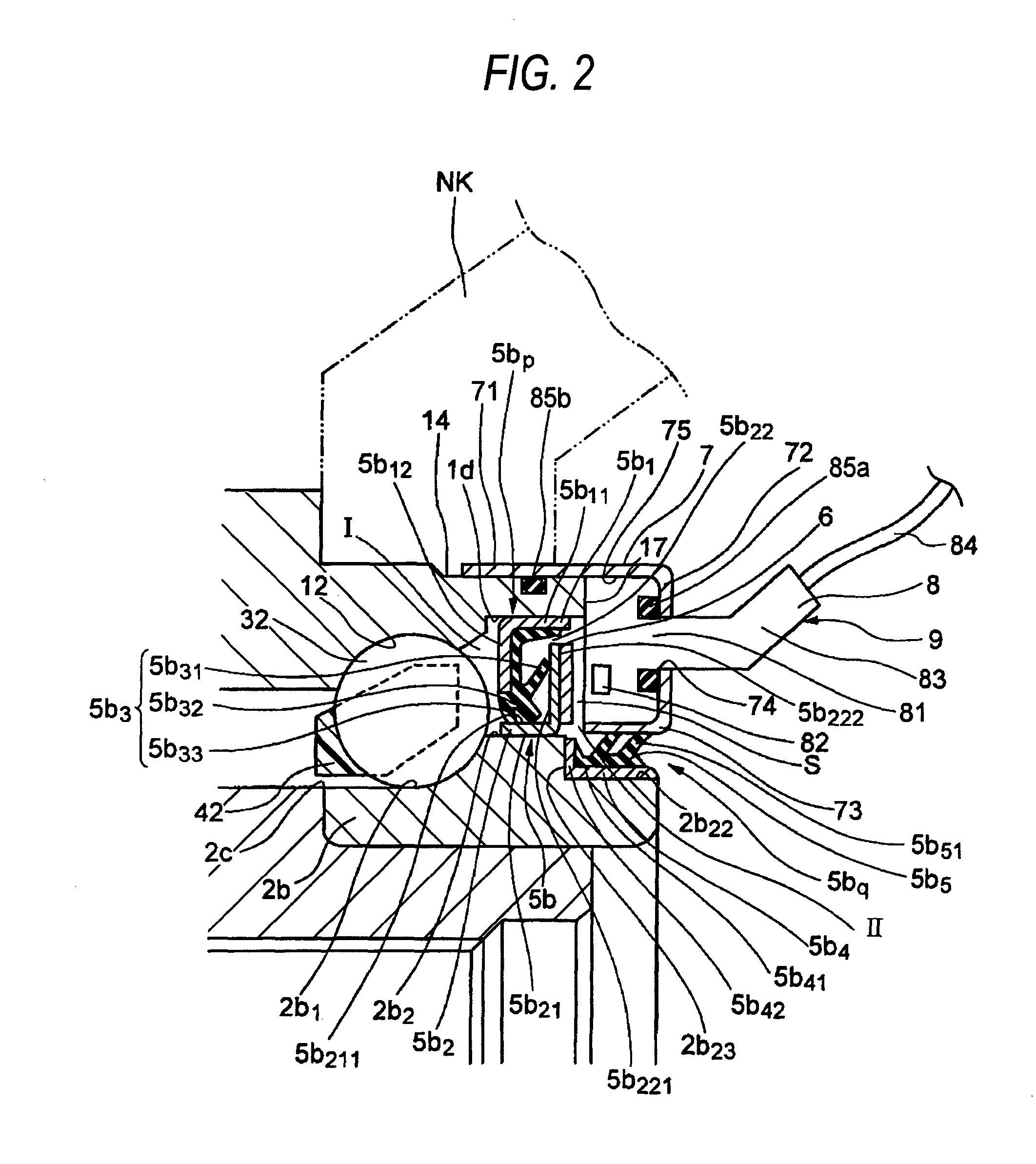
[0032][FIG. 4] A diagram corresponding to FIG. 2, which shows Modified Example 2 of Embodiment 1.

[0033][FIG. 5] A diagram corresponding to FIG. 2, which shows Modified Example 3 of Embodiment 1.

[0034][FIG. 6] A diagram corresponding to FIG. 2, which shows Modified Example 4 of Embodiment 1.

[0035][FIG. 7] A diagram corresponding to FIG. 2, which shows Modified Example 5 of Embodiment 1.

[0036][FIG. 8] A diagram corresponding to FIG. 2, which shows Modified Example 6 of Embodiment 1.

DESCRIPTION OF REFERENCE NUMERALS AND CHARACTERS

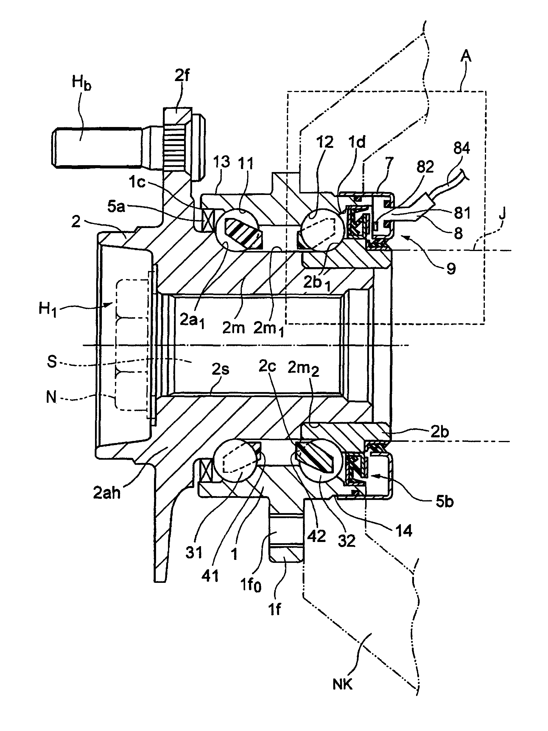
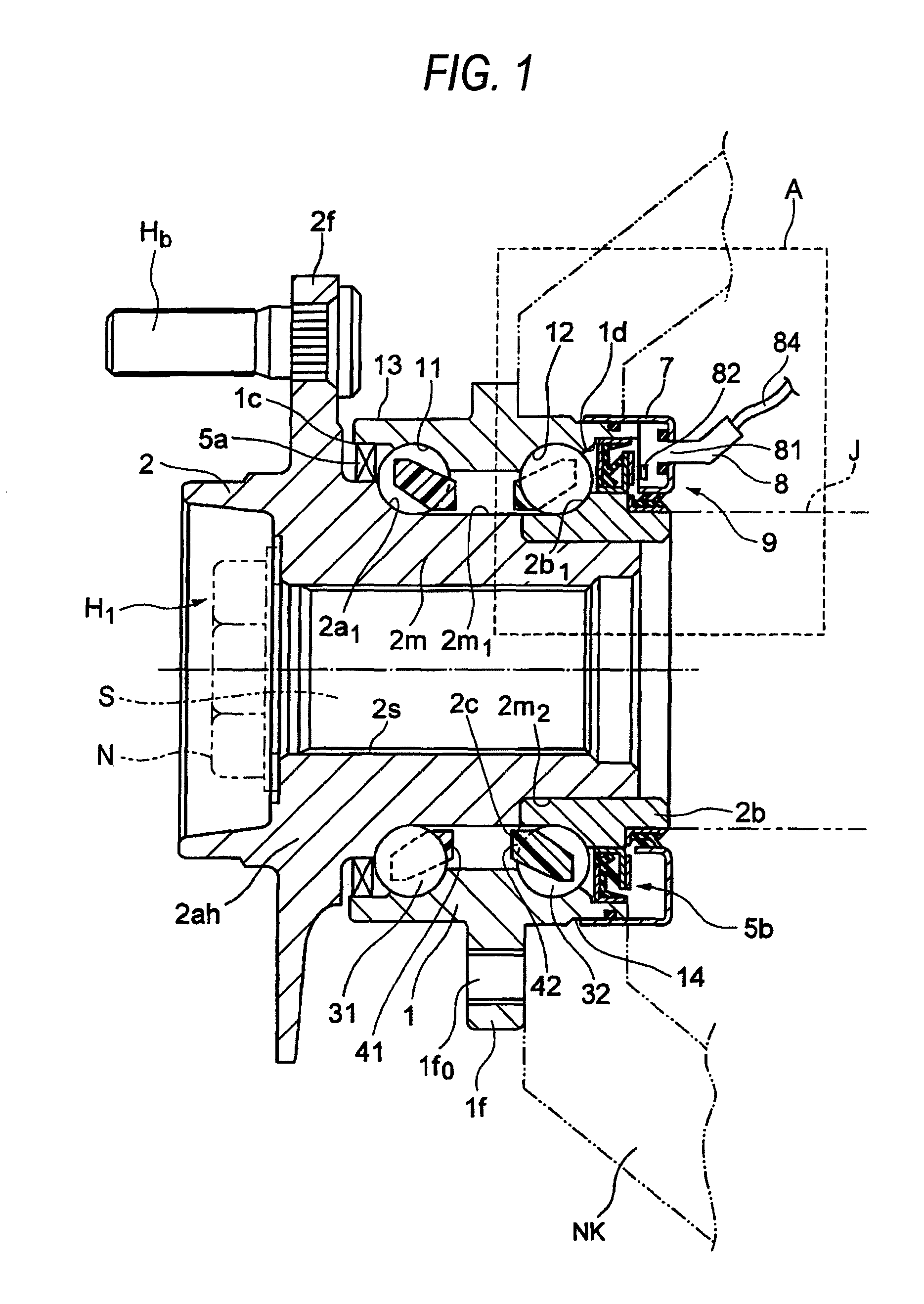
[0037]H1, H2: hub unit bearing

[0038]1: outer ring

[0039]11, 12: inner circumferential raceway

[0040]13: outermost side facing outer ring end portion

[0041]14: center side facing outer ring end portion

[0042]1f0: mounting flange

[0043]2: inner ring

[0044]2a, 2b: inner ring element

[0045]2a1, 2b1: outer circumferential raceway

[0046]2ah: hub shaft

[0047]2c: stepped portion

[0048]2f: hub flange

[0049]2m: cylindrical portion

[0050]2m1: outermost side facing cylindrical port...


PUM


Abstract

A hub unit bearing H1 includes a rotational speed detector 9 which is made up of an encoder 6 and a sensor 8. A seal 5b on a side facing a center side of a vehicle includes a primary seal 5bp and a secondary seal 5bq which are disposed in that order in an axial direction from rolling elements 32 on a side facing the center side of the vehicle towards the center side of the vehicle so as to define a primary sealed space portion I between the vehicle's center side facing rolling elements 32 and the primary seal 5bp and a secondary sealed space portion II between the primary seal 5bp and the secondary seal 5bq, with the rotational speed detector 9 disposed within the secondary sealed space portion II.

Description

TECHNICAL FIELD[0001]The present invention relates to a hub unit bearing including a rotational speed detector.BACKGROUND ART[0002]Recently, there has been an increasing tendency that hub unit bearings for wheels include a rotational speed detector having installed therein an encoder made up of a multipolar magnet and an active sensor employing a Hall element or MR element in association with spread of ABS (Anti-lock Brake System).[0003]As seen in JP-A-2002-333033, for example, there is an increasing number of multipolar magnets incorporating encorders which has a construction in which an encoder is fabricated integrally into a seal of a bearing so as to be installed in a hub unit bearing as a seal with an encoder.[0004]However, in the case of a hub unit bearing for a driven wheel, since a constant velocity joint for driving the wheel exits on a center side of a vehicle while lying adjacent to a hub unit bearing, a problem is caused that there is no space for installation of a senso...

Claims


Application Information

Patent Timeline
Patent Type & Authority Patents(United States)
IPC IPC(8): F16C33/76F16C32/00F16C13/00
CPCB60B27/00F16C41/007F16J15/326G01P1/023G01P3/443F16C33/7883F16C33/7896F16C19/186F16C2326/02B60B27/0068B60B27/0073
Inventor KANEKO, YOSHIOSHIBUYA, EISHIHASHIDA, MASARU
Owner NSK LTD
Learn More