Imaging apparatus and imaging control method

a technology of imaging control and imaging apparatus, which is applied in the field of imaging apparatus, can solve the problems that the adjustment might not suitably reflect the contrast in the scene, and achieve the effect of favorable composite image and dynamic rang

Active Publication Date: 2013-04-16
SONY CORP
View PDF10 Cites 4 Cited by
  • Summary
  • Abstract
  • Description
  • Claims
  • Application Information

AI Technical Summary

Benefits of technology

[0006]However, although the short-exposure time is automatically adjusted in the imaging apparatus disclosed in the above JP-A-2008-271368, the adjustment might not suitably reflect the contrast in the scene. If, for example, the imaging apparatus were configured to determine the luminance range (i.e., the difference between the maximum and minimum luminance) of the subject, and then set different exposure times according to the luminance range, then it would be possible effectively utilize the dynamic range of the imaging element (i.e., the imaging means) and generate a favorable composite image.
[0009]According to an embodiment of the present invention, the luminance range in accordance with a subject is detected, and the range of exposure control values is set having steps that correspond to the value obtained by multiplying the luminance range by a predetermined coefficient k (where 0<k<1). An imaging unit or similar means is then used to take multiple shots set at respectively different exposure control values within the range of exposure control values. Image portions extracted from the plurality of images obtained by taking multiple shots are then composited to generate a composite image. Herein, when just one shot is taken, the single exposure control value set for the one shot is contained within the range of the exposure control values. As a result, the dynamic range of the imaging means is effectively utilized, and a favorable composite image is generated by taking multiple shots that suitably reflect the luminance range of the subject.

Problems solved by technology

However, although the short-exposure time is automatically adjusted in the imaging apparatus disclosed in the above JP-A-2008-271368, the adjustment might not suitably reflect the contrast in the scene.

Method used


Image

  • Imaging apparatus and imaging control method
  • Imaging apparatus and imaging control method
  • Imaging apparatus and imaging control method

Examples


first embodiment

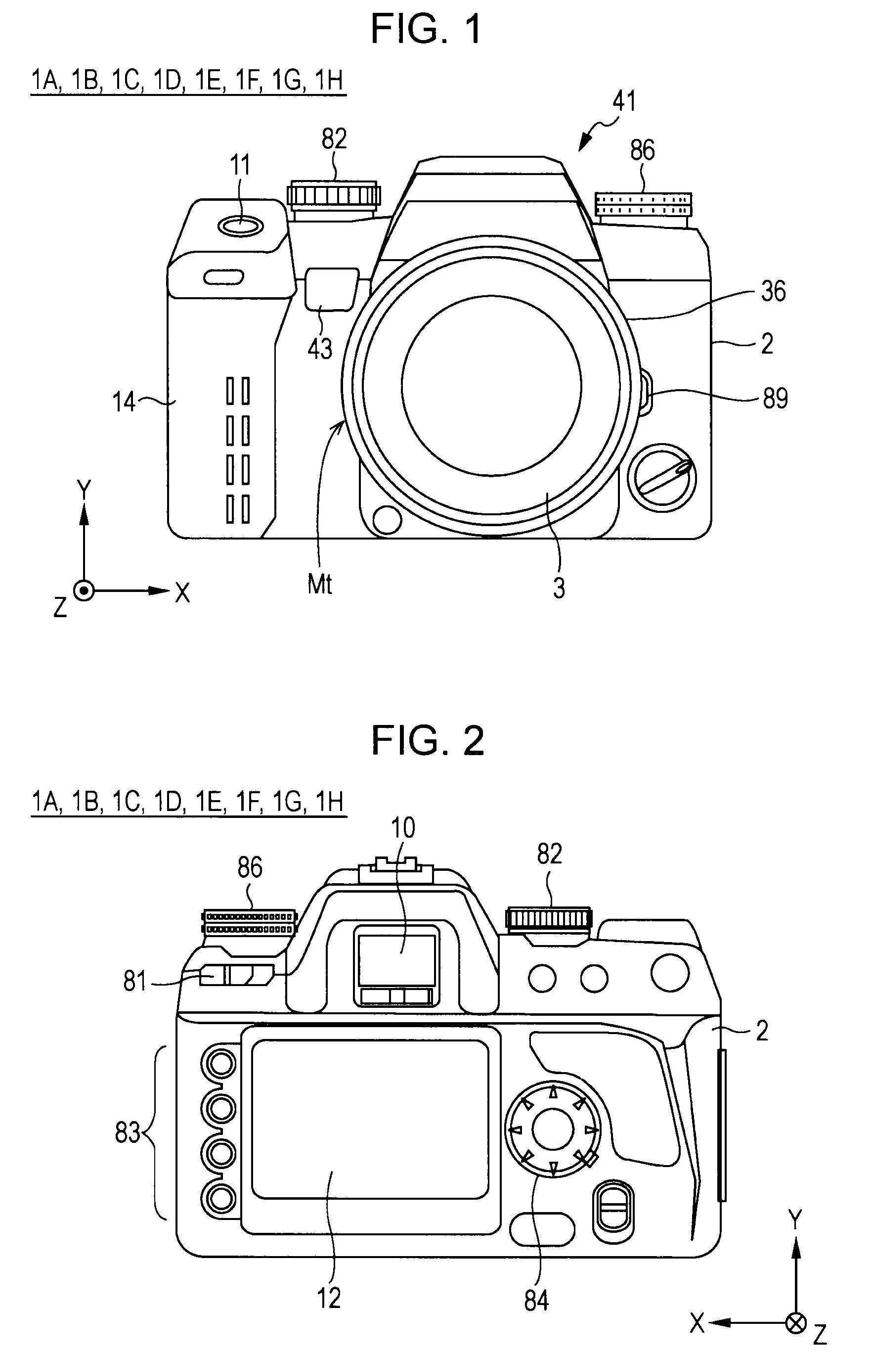
[0031]FIGS. 1 and 2 illustrate the external configuration of an imaging apparatus 1A in accordance with the present invention. FIG. 1 is a front exterior view of the imaging apparatus 1A, while FIG. 2 is a rear exterior view of the imaging apparatus 1A. The imaging apparatus 1A herein is configured as a lens-interchangeable, digital single-lens reflex (DSLR) camera.

[0032]As shown in FIG. 1, the imaging apparatus 1A is provided with a camera body 2. The interchangeable lens 3, an interchangeable photographic lens unit, is freely attachable to and detachable from the camera body 2.

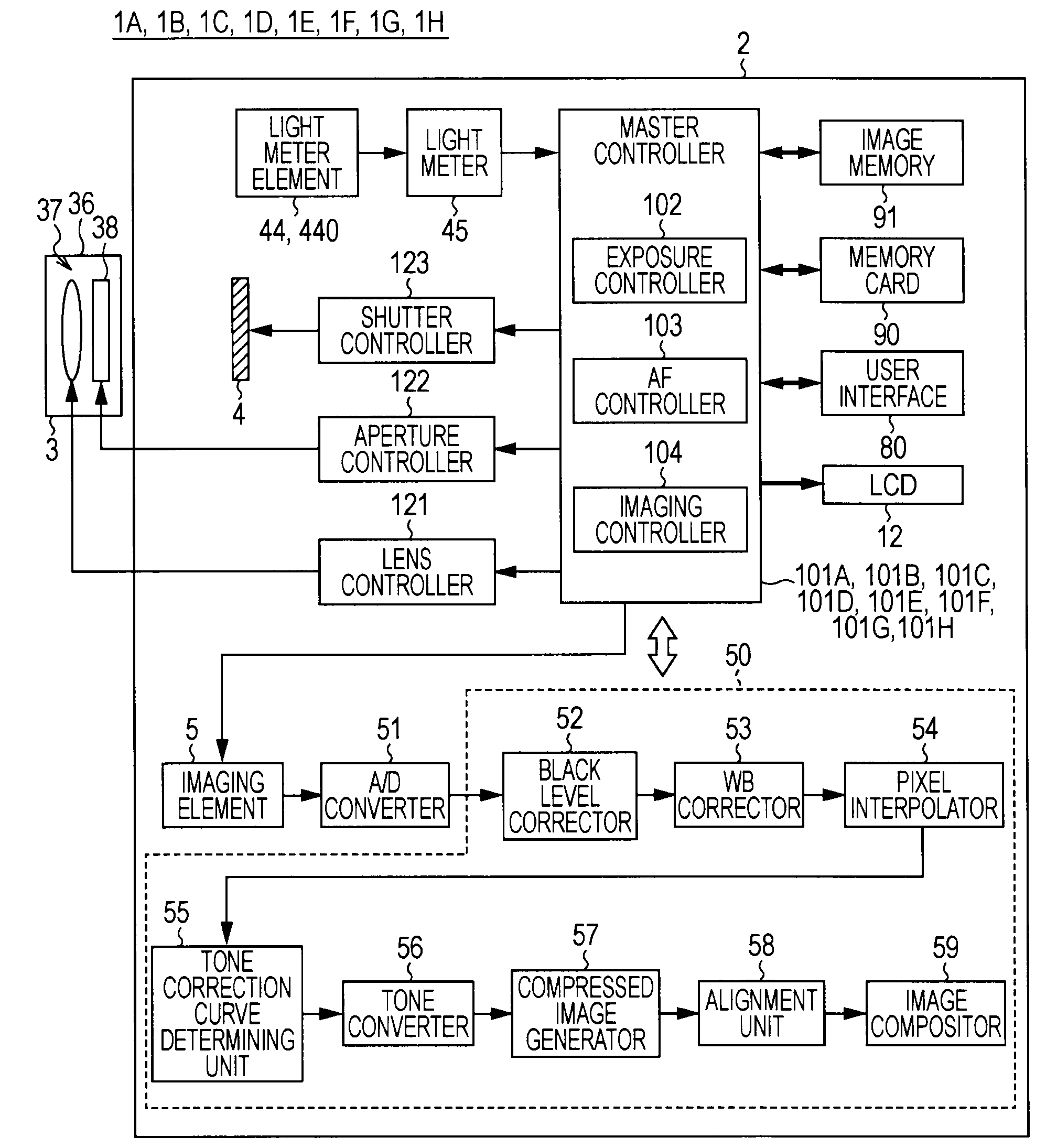
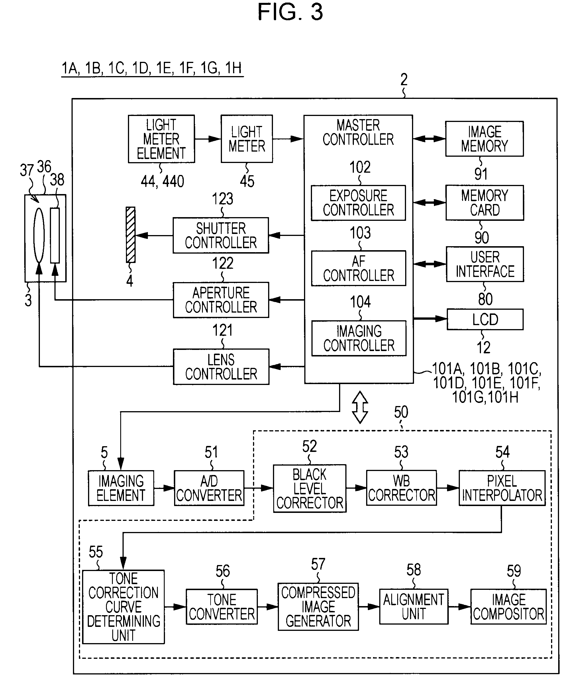
[0033]The interchangeable lens 3 primarily includes a lens tube 36, as well as a lens group 37 (see FIG. 3) and an aperture 38 (see FIG. 3) provided inside the lens tube 36. The lens group 37 acts as the imaging optics, and includes lenses such as a focus lens for adjusting the focal point by moving along the optical axis.

[0034]In approximately the center of the front side of the camera body 2, there is prov...

second embodiment

[0094]In other words, the master controller 101B of the second embodiment stores in ROM a program that executes the operation described hereinafter.

[Operation of Imaging Apparatus 1B]

[0095]FIG. 9 is a flowchart illustrating the basic operation of the imaging apparatus 1B. FIG. 9 shows the exposure control operation for the case wherein the Multi-Segment Metering mode is set, and wherein the above-described Aperture Priority mode is set as the exposure mode. The exposure control operation shown in FIG. 9 is executed by the master controller 101B.

[0096]In step ST11, operation is conducted similar to that of step ST1 in the flowchart shown in FIG. 8.

[0097]In step ST12, a suitable exposure control value is determined for normal shooting (i.e., the case of taking a single shot) wherein the user has used the control value dial 86 to specify a particular aperture value setting. More specifically, the suitable exposure control value Bcnt for normal shooting is calculated by means of predete...

third embodiment

[0104]In other words, the master controller 101C of the third embodiment stores in ROM a program that executes the operation described hereinafter.

[Operation of Imaging Apparatus 1C]

[0105]FIG. 10 is a flowchart illustrating the basic operation of the imaging apparatus 10. FIG. 10 shows the exposure control operation for the case wherein the Multi-Segment Metering mode is set, and wherein the above-described Shutter Speed Priority mode is set as the exposure mode. The exposure control operation shown in FIG. 10 is executed by the master controller 101C.

[0106]In step ST21, operation is conducted similar to that of step ST1 in the flowchart shown in FIG. 8.

[0107]In step ST22, a suitable exposure control value is determined for normal shooting (i.e., the case of taking a single shot) wherein the user has used the control value dial 86 to specify a particular shutter speed TVs. More specifically, the suitable exposure control value Bcnt for normal shooting is calculated by means of prede...


PUM


Abstract

In an imaging apparatus, an imaging unit generates an acquired image of a subject. A luminance information acquirer acquires the subject's luminance information. A detector detects the subject's luminance range on the basis of the acquired luminance information. An imaging controller sets a range of exposure control values having a step that corresponds to a value obtained by multiplying the detected luminance range by a predetermined coefficient k (where 0<k<1), and then uses the imaging unit to take multiple shots (i.e., multiple imagings) set with respectively different exposure control values within the range of exposure control values. An image compositor generates a composite image by compositing image portions extracted from the plurality of images obtained via the multiple shots. When just one shot is taken, the single exposure control value set for the one shot is contained within the range of the exposure control values.

Description

BACKGROUND OF THE INVENTION[0001]1. Field of the Invention[0002]The present invention relates to an imaging apparatus provided with an imaging unit that generates an acquired image of a subject.[0003]2. Description of the Related Art[0004]When a digital camera or similar imaging apparatus is used to shoot a scene with high contrast (such as backlit shooting, or simultaneously shooting indoors and outdoors), loss of detail may occur due to insufficient dynamic range of the imaging element. In other words, the bright portions of the image may become saturated and blown out (i.e., overexposed), while the dark portions may become blocked up (i.e., underexposed). Such loss of detail can occur even when exposure control is performed.[0005]Technology for alleviating the above defect has been disclosed, wherein an imaging apparatus generates a high dynamic range composite image by compositing a long-exposure image and a short-exposure image obtained by shooting twice with different exposure...

Claims


Application Information

Patent Timeline
Patent Type & Authority Patents(United States)
IPC IPC(8): H04N5/235
CPCH04N5/23293H04N5/2353H04N5/35536H04N5/361H04N23/632H04N23/73H04N25/58H04N25/63H04N23/843
Inventor UEDA, ATSUSHIMINAKUTI, JUN
Owner SONY CORP
Why Eureka
Try Eureka