Method for manufacturing thermally-assisted magnetic recording head by semi-active alignment

a technology of magnetic recording head and magnetic recording medium, which is applied in special recording techniques, instruments, and record information storage, etc., can solve the problems of deterioration in the thermal stability of the magnetization, the head cannot write data to the magnetic recording medium, and the problem of more significant problems to be solved, so as to achieve high alignment accuracy and short processing time

Active Publication Date: 2013-04-23
TDK CORPARATION
View PDF28 Cites 10 Cited by
  • Summary
  • Abstract
  • Description
  • Claims
  • Application Information

AI Technical Summary

Benefits of technology

[0027]This manufacturing method according to the present invention utilizes an alignment method that uses a light for alignment that is entered into the light source from the opposite side to the light-emission center and is emitted from the light-emission center. This alignment method is hereinafter referred to as “semi-active alignment”. The “semi-active alignment” can achieve the alignment of the light source unit and the slider with a sufficiently high alignment accuracy in a short processing time.

Problems solved by technology

However, the decrease in size of the magnetic grains raises a problem of degradation in thermal stability of the magnetization due to the decrease in volume.
As a result, the head cannot write data to the magnetic recording medium when the anisotropic magnetic field of the medium exceeds the write field limit.
However, from the beginning, more significant problem to be solved exists in where and how a light source with a sufficiently high output of light should be disposed inside a head.
However, the active alignment is a method of merely locating a two-dimensional optimum position and has the drawback of requiring a considerably long time for alignment.
In addition, power supply probes need to be applied to the electrodes of the light source in order to keep activating the light source during the alignment, which further increase the time required for the alignment.
Furthermore, a head structure and probing facilities which are required for the probing increase the manufacturing load.
However, the accuracy of the passive alignment tends to be low compared with the active alignment.
In addition, it is considerably difficult to find or add a marker for the passive alignment on the light-source unit during fabrication of a head having the “composite slider structure”.
If the light source is an edge-emitting laser diode, an end of a ridge structure located at the light-emitting surface of the diode is as small as approximately 2×2 μm2, for example, and is difficult to observe.
Furthermore, even if the end can be observed, it is extremely difficult to identify the light-emission center in the end of the ridge structure.
However, provision of a light source, such as a laser diode, to which a maker suitable for image recognition is given will significantly increase manufacturing cost.

Method used


Image

  • Method for manufacturing thermally-assisted magnetic recording head by semi-active alignment
  • Method for manufacturing thermally-assisted magnetic recording head by semi-active alignment
  • Method for manufacturing thermally-assisted magnetic recording head by semi-active alignment

Examples


Embodiment Construction

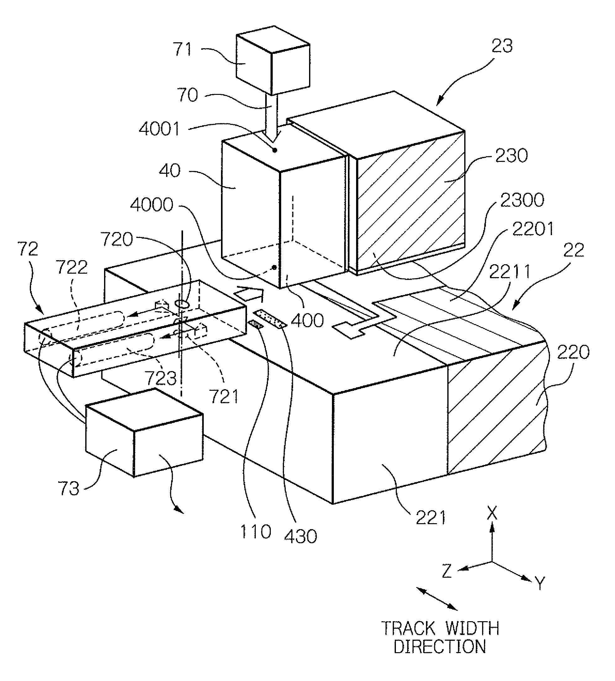
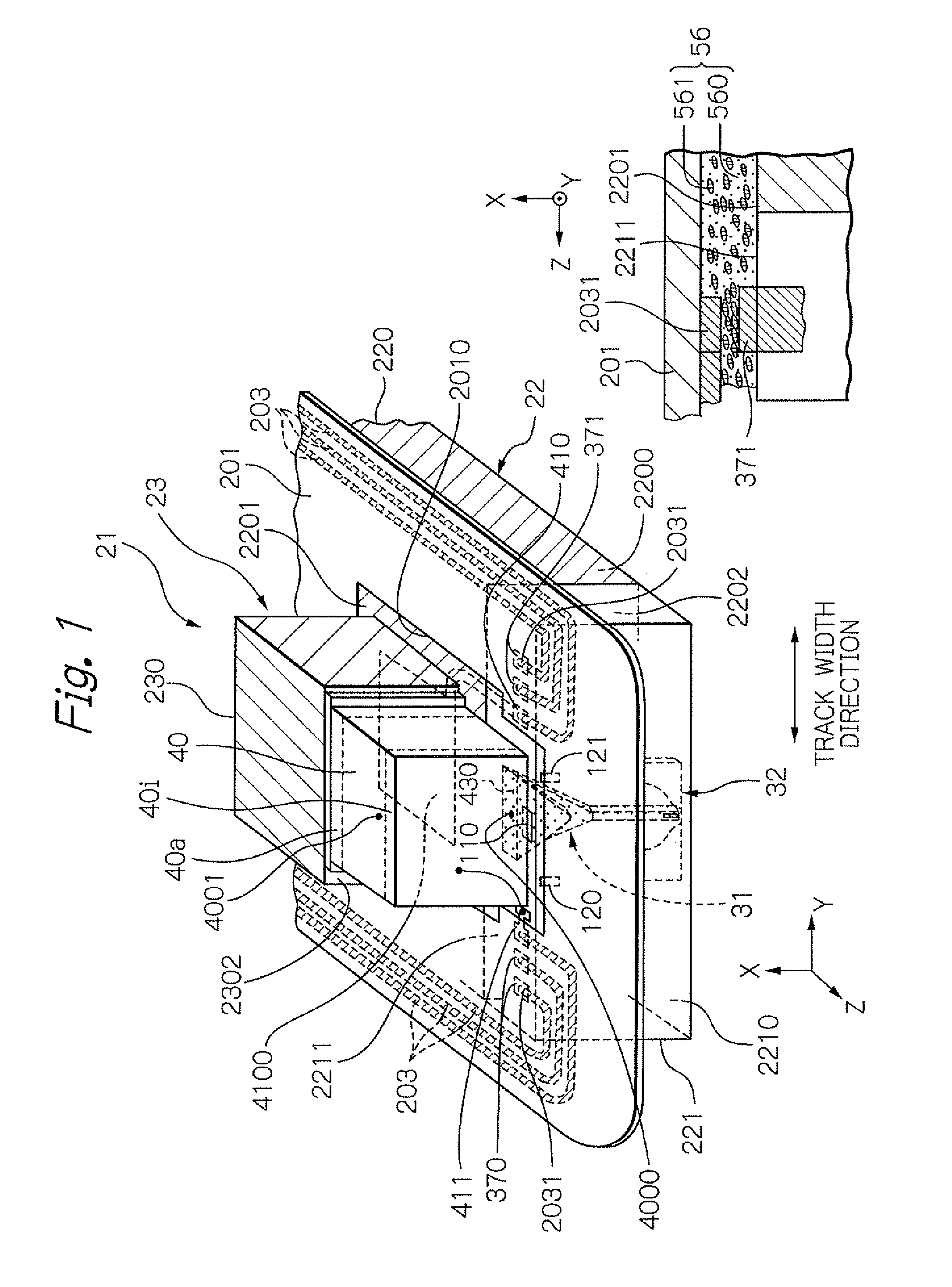
[0046]FIG. 1 shows a perspective view and a cross-sectional view schematically illustrating an embodiment in which a thermally-assisted magnetic recording head 21 according to the present invention is attached on a flexure 201 of a head gimbal assembly (HGA). In the perspective view, the side of the head 21 opposed to the surface of the magnetic disk is turned downward.

[0047]As shown in FIG. 1, the thermally-assisted magnetic recording head 21 is constituted by joining a light source unit 23 including a laser diode 40 as a light source to a slider 22. The slider 22 includes a slider substrate 220 and a head element part 221 provided on the element-integration surface of the slider substrate 220. The head element part 221 includes: an optical system 31 for guiding laser light generated from the laser diode 40 toward the opposed-to-medium surface side and for generating a light (near-field light) for thermal assist; and a head element 32 for writing and reading data. Further, a flexur...


PUM

PropertyMeasurementUnit
distanceaaaaaaaaaa
distanceaaaaaaaaaa
distanceaaaaaaaaaa

Abstract

A method for manufacturing a thermally-assisted magnetic recording head is provided, in which joined are: a light source unit that includes a light source having a surface including a light-emission center on the joining surface side of a unit substrate; and a slider that includes an optical system having a light-receiving end surface reaching a back surface opposite to the opposed-to-medium surface. This method utilizes “semi-active alignment” that uses an alignment light, and comprises steps of: causing a light to enter the light source from a surface opposite to the light-emission center; detecting the light that has passed through the light source and is emitted from the light-emission center to align the light-emission center with the light-receiving end surface of the slider; and bonding the light source unit to the slider. This manufacturing method can achieve the alignment with a sufficiently high alignment accuracy in a short processing time.

Description

BACKGROUND OF THE INVENTION[0001]1. Field of the Invention[0002]The present invention relates to a thermally-assisted magnetic recording head fabricated by joining a slider and a light source unit that includes a light source, and further relates to a method for manufacturing the thermally-assisted magnetic recording head.[0003]2. Description of the Related Art[0004]As the recording densities of magnetic recording apparatuses become higher, as represented by magnetic disk apparatuses, further improvement has been required in the performance of thin-film magnetic heads and magnetic recording media. As the thin-film magnetic heads, a composite-type thin-film magnetic head is widely used, which has a stacked structure of a magnetoresistive (MR) element for reading data and an electromagnetic transducer for writing data.[0005]Whereas, the magnetic recording medium is generally a kind of discontinuous body of magnetic grains gathered together, and each of the magnetic grains has a single...

Claims


Application Information

Patent Timeline
Patent Type & Authority Patents(United States)
IPC IPC(8): G11B11/12
CPCG11B5/314G11B5/6088G11B5/3163G11B2005/001Y10T29/49055Y10T29/49037Y10T29/49059Y10T29/49032G11B2005/0021
Inventor SHIMAZAWA, KOJITAKAYAMA, SEIICHIKOMURA, EIJISHINDO, OSAMUHONDA, TAKASHI
Owner TDK CORPARATION
Why Eureka
Try Eureka