Method for manufacturing a pole for a magnetic recording head

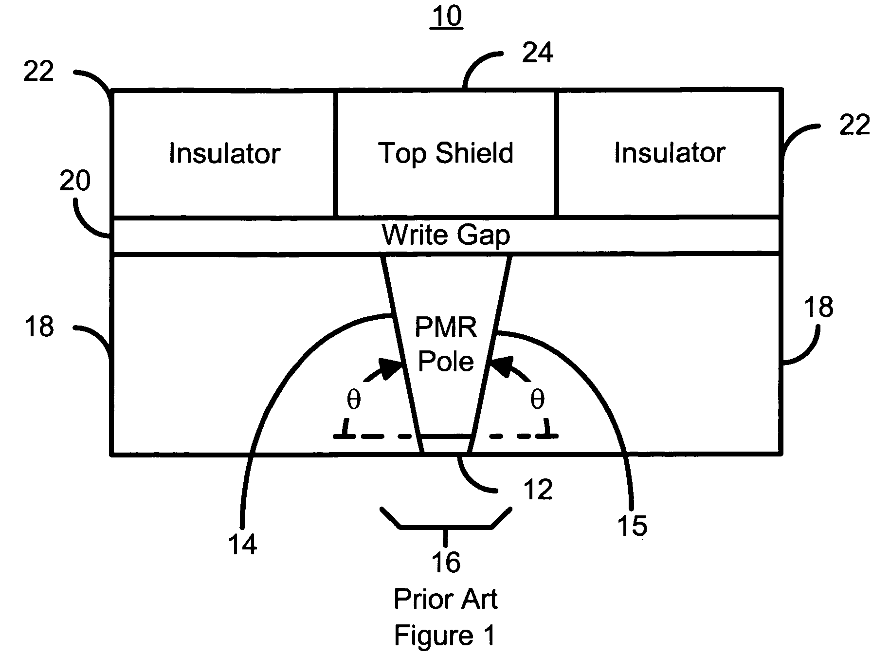
a manufacturing method and magnetic recording technology, applied in the field of methods, can solve the problems of undesirably low yield of conventional poles, difficult repeatability of fabrication of suitable conventional poles b>10/b>, and difficulty in controlling the height of conventional poles b>16/b>,

Inactive Publication Date: 2013-04-23
WESTERN DIGITAL TECH INC
View PDF21 Cites 147 Cited by
  • Summary
  • Abstract
  • Description
  • Claims
  • Application Information

AI Technical Summary

Benefits of technology

[0008]FIG. 1 is diagram depicting a conventional perpendicular magnetic recording pole.
[0009]FIG. 2 is a flow chart depicting a conventional method for fabricating a perpendicular magnetic recording pole.

Problems solved by technology

As a result, the height of the conventional pole 16 may be extremely difficult to control and fabrication of suitable conventional PMR heads 10 may be difficult to repeat.
Manufacturing of conventional PMR heads 10 may, therefore, have an undesirably low yield.

Method used


Image

  • Method for manufacturing a pole for a magnetic recording head
  • Method for manufacturing a pole for a magnetic recording head
  • Method for manufacturing a pole for a magnetic recording head

Examples


Embodiment Construction

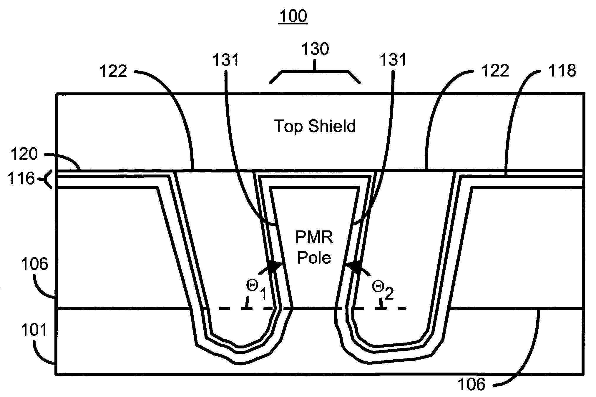
[0015]FIGS. 3A-3G depict a PMR head 100 formed in accordance with an exemplary embodiment of the present invention. To enhance clarity, FIGS. 3A-3F are not drawn to scale. In addition, although a PMR head is depicted, the method and system may be used with a different head, such as a longitudinal recording head. FIG. 3A depicts the PMR head 100 after the material(s) 102 for the pole has been sputtered. The materials 102 could form a multilayer structure so that the resulting pole is a laminated structure. The material(s) 102 could also include alloys. The resulting pole is ferromagnetic, but in some embodiments, the material(s) 102 sputtered could include nonmagnetic materials as well as ferromagnetic materials. For example, the material(s) 102 may include CoFe, CoFeN, CoNiFe, CoFe / Ru, CoFe / Cr, as well as other materials.

[0016]FIG. 3B depicts the PMR head 100 after a smaller region 104 of the ferromagnetic materials has been defined, for example by masking and ion milling a portion ...


PUM

PropertyMeasurementUnit
angleaaaaaaaaaa
angleaaaaaaaaaa
angleaaaaaaaaaa

Abstract

A method and system for manufacturing a pole on a recording head is disclosed. The method and system include sputtering at least one ferromagnetic layer and fabricating a hard mask on the ferromagnetic layer. The method and system also include defining the pole and depositing a write gap on the pole. A portion of the pole is encapsulated in an insulator.

Description

FIELD OF THE INVENTION[0001]The present invention relates to magnetic recording technology and more particularly to a method and system for providing a sputtered pole for a magnetic recording head.BACKGROUND OF THE INVENTION[0002]A conventional magnetic recording head includes a transducer deposited on a back surface of a slider. The slider also includes an air-bearing surface (ABS) that faces the recording media. FIG. 1 depicts a portion of conventional perpendicular magnetic recording (PMR) transducer 10 as viewed looking towards the ABS (not shown). The conventional PMR transducer 10 includes a conventional pole 16 and a top shield 24 separated by a write gap 20. Note that the top shield 24 also acts as pole during writing using the conventional PMR transducer 10. The conventional pole 16 and the top shield 24 are surrounded by insulating layers 18 and 22. The conventional pole 16 resides on a seed layer 12 and has sidewalls 14 and 15.[0003]In conventional applications, the heigh...

Claims


Application Information

Patent Timeline
Patent Type & Authority Patents(United States)
IPC IPC(8): G11B5/127H04R31/00
CPCG11B5/1278G11B5/3116G11B5/3163G11B5/3169Y10T29/49046Y10T29/49052Y10T29/49048Y10T29/49041Y10T29/49044Y10T29/49043
Inventor YANG, DANNINGWANG, LEICHEN, YINGJIANNEASE, BRANTSIN, KYUSIK
Owner WESTERN DIGITAL TECH INC
Why Eureka
Try Eureka