Aerosol transport system

Inactive Publication Date: 2013-04-23
AIR FORCE UNITED STATES OF AMERICA AS REPRESENTED SEC OF THE THE
View PDF6 Cites 0 Cited by
  • Summary
  • Abstract
  • Description
  • Claims
  • Application Information

AI Technical Summary

Benefits of technology

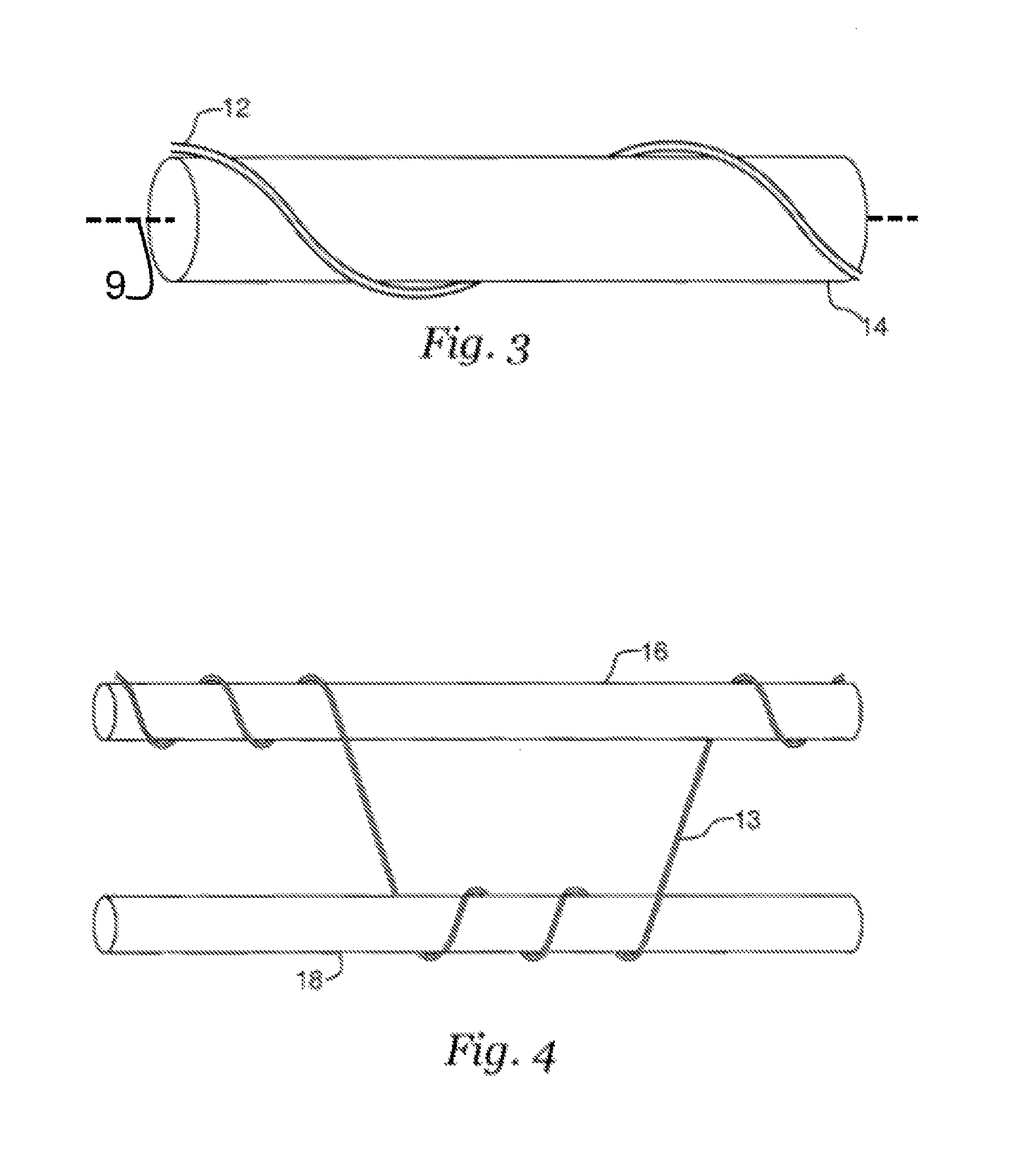
[0007]Broadly, the present invention provides a method of reducing the settling of particles during transport of an aerosol in a tube over long distances and includes configuring the tube in a coil about a

Problems solved by technology

Current means for transporting aerosol particles horizontally are limited.
Generally, particles with diameters larger than 5 microns can only be transported for limited distances or with very low transport efficiency.
Losses in straight tubes are high due to competing mechanisms.
At high speeds, turbulent inertial losses dominate.
If there are bends in the t

Method used


Image

  • Aerosol transport system
  • Aerosol transport system
  • Aerosol transport system

Examples


example i

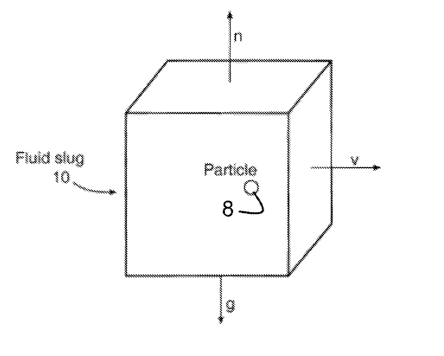
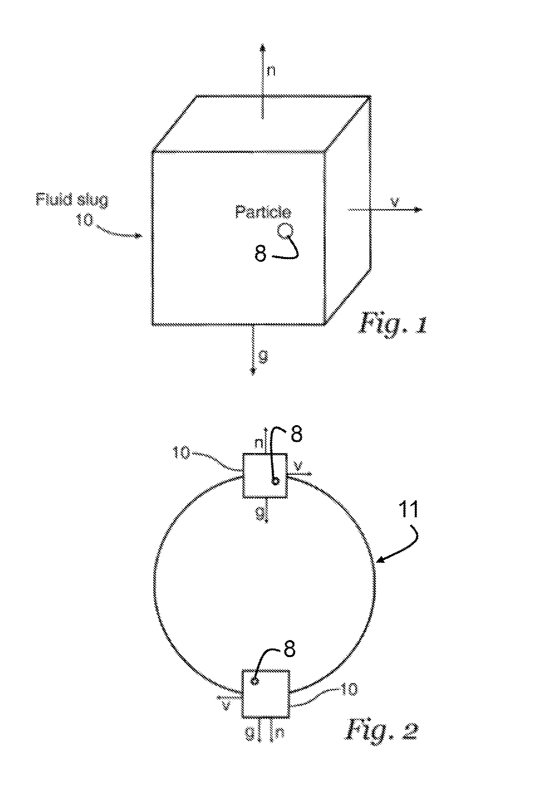
[0029]In operation, an aerosol transport is employed for aerosol transport through a tube across a building. The 10 μm size particles employed have a sedimentation velocity of about 0.3 cmfs. The transport distance is 100 meters, the tube diameter is 1 cm, and the guide radius is 1 cm. Let the length L (of full particle rotation in the tube) be 20 cm. Finally, let the velocity be 100 cmfs. In this case, the transit time is about 20 seconds and the Reynolds number is about 600. Let N be 2. Then the maximum displacement downward due to gravity is 0.06 cm and the maximum displacement radially due to centrifugal force is 0.12 cm.

[0030]Thus it can be seen how novel and useful the aerosol transport system of the invention is. That is, it is a means for transporting relatively large aerosol particles over long distances inside a tube to arrive at a destination with greatly reduced particle fall-out or losses due to gravity or centrifugal forces.

[0031]Commercial Applications of the aerosol ...


PUM


Abstract

An aerosol transport system. The aerosol transport system comprising a tube and having a plurality of windings that permit the flow of aerosols, including particles, there-through so as to compensate for gravity and/or centrifugal forces and reduce the settling of particles within said tube.

Description

STATEMENT OF GOVERNMENT INTEREST[0001]The invention described herein may be manufactured and / or used by or for the Government for governmental purposes without the payment of any royalty thereon.FIELD OF THE INVENTION[0002]This invention relates to transporting aerosol over horizontal, or near horizontal distances, in a tube with reduced particle settling in such tube.BACKGROUND OF THE INVENTION[0003]In many situations, it is desirable to transport aerosol over long distances. For example, aerosol collectors may be mounted in one location and aerosol detectors may be mounted elsewhere. Or it can be desirable to multiplex one detector to many collectors. Current means for transporting aerosol particles horizontally are limited. Generally, particles with diameters larger than 5 microns can only be transported for limited distances or with very low transport efficiency. Typical transport means are a straight tube. Straight tubes transport small particle sizes efficiently only over limi...

Claims


Application Information

Patent Timeline
IPC IPC(8): B05B1/34
CPCG01N1/22G01N1/2273G01N2015/0046G01N2001/2285
Inventor HEFF, ALLANUTTARO, RAYMOND S.
Owner AIR FORCE UNITED STATES OF AMERICA AS REPRESENTED SEC OF THE THE
Why Eureka
Try Eureka