Static free method for blowing loose fill insulation

Inactive Publication Date: 2003-01-07
US GREENFIBER
View PDF23 Cites 86 Cited by
  • Summary
  • Abstract
  • Description
  • Claims
  • Application Information

AI Technical Summary

Benefits of technology

It is, therefore, an object of the invention to provide an apparatus and method of

Problems solved by technology

During installation, the insulation material scattered widely as it exited the hose, creating a considerable dust problem that materially obs

Method used


Image

  • Static free method for blowing loose fill insulation
  • Static free method for blowing loose fill insulation
  • Static free method for blowing loose fill insulation

Examples


Embodiment Construction

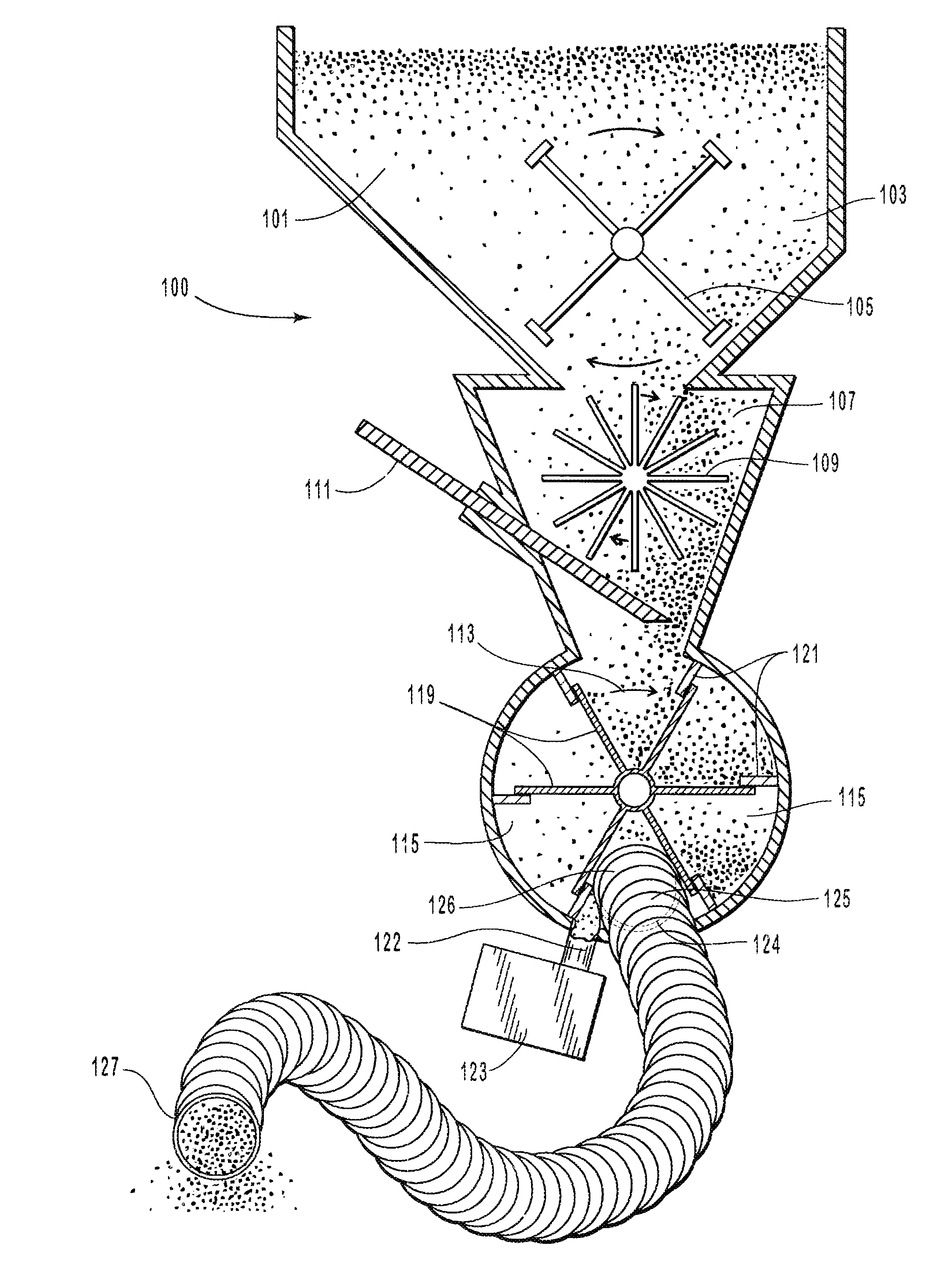
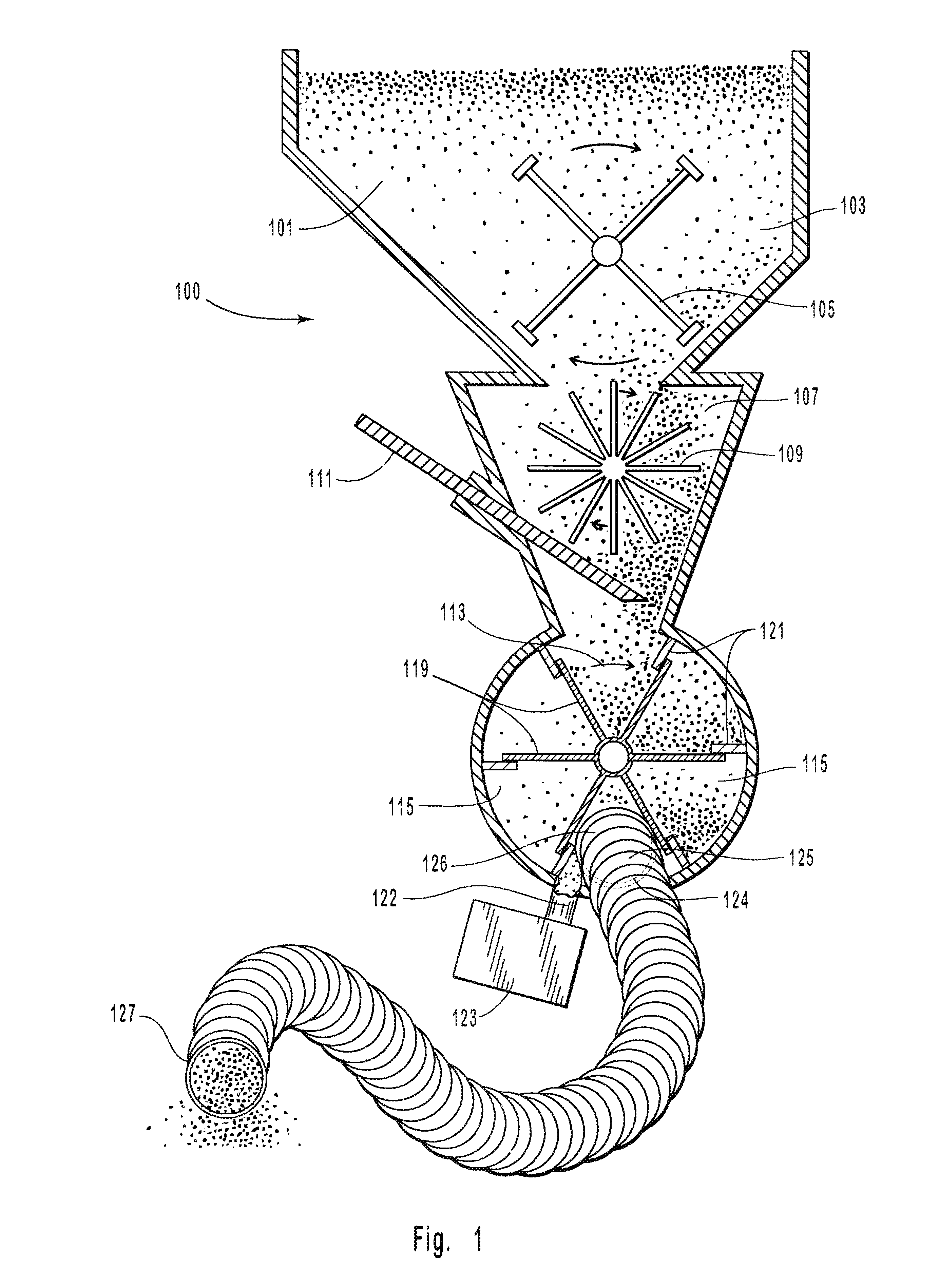
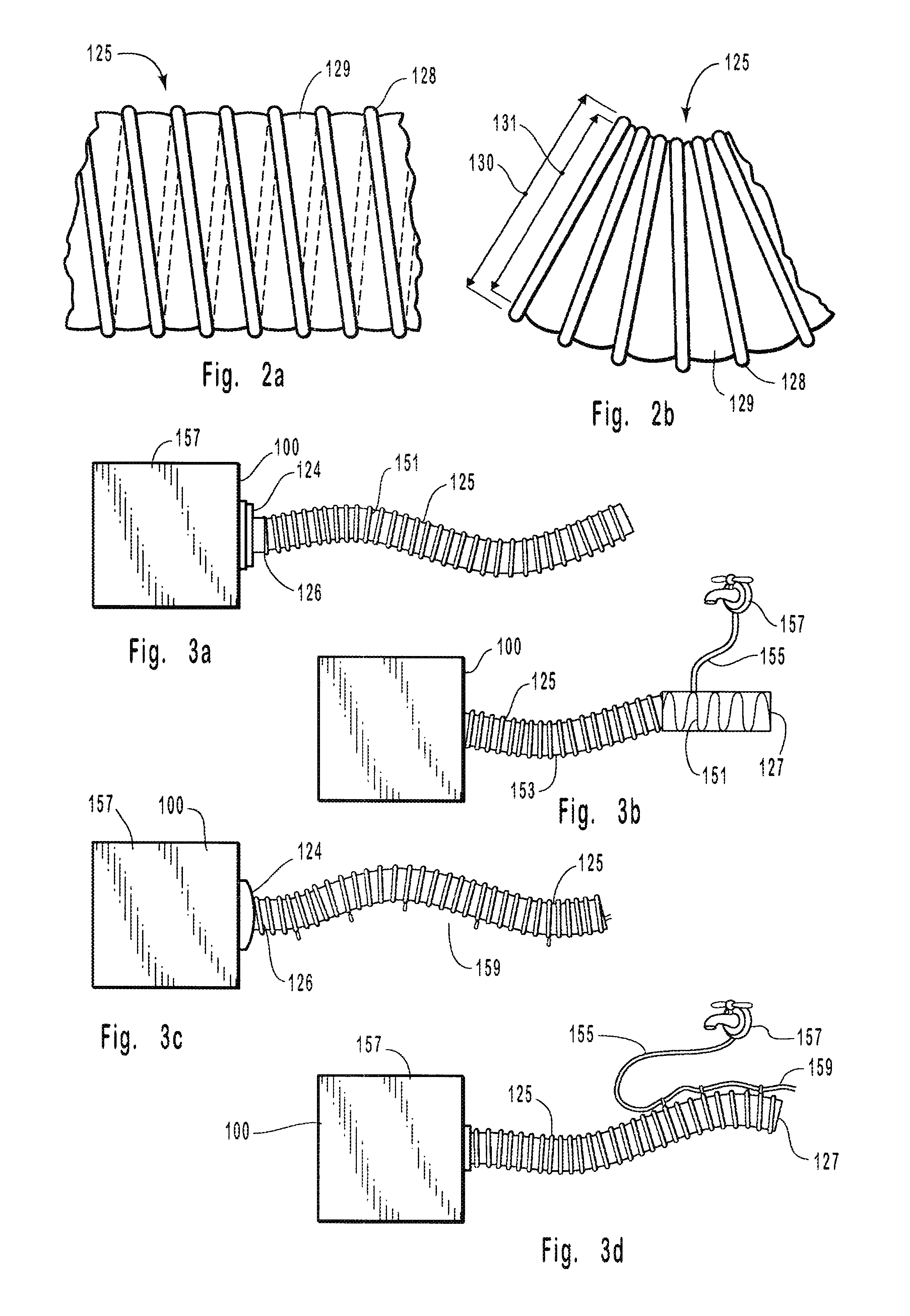
The same insulation material was applied by blowing according to the method of the invention. The equipment was essentially the same as in the previous example, except the hose was of a conductive material grounded to the blower. The hose was the same dimension as the conventional plastic hose and comprised a polyethylene helical frame supporting in its interior a film hose of conductive carbon impregnated plastic. During installation of the insulation, there was little dust and application of the insulation material was readily observable, which made it easier to control the application. The operator experienced no shocks, even when he touched a grounded surface. The flow rate the insulation through the hose was 3200 pounds per hour, an increase of 15% over the flow rate in the prior-art example.

The blown density was about 1.65 pounds per cubic foot, which settled over the same time to a settled density of 1.8 pounds per cubic foot. The increase in density was only about 9%. The se...


PUM


Abstract

An apparatus and method for installing blown installation where insulation is entrained in a stream of air and is blown through an electrostatic dissipating hose. The hose contains an electrically conductive and grounded element to dissipate the static charges built up in the entrained insulation passing through the hose and exiting the hose for application into a selected space.

Description

(Not applicable)(Not applicable)This invention relates to a method and apparatus for applying blown insulation.A common method of applying insulation into cavities, such as attic spaces and the like, is to blow the insulation into place. This type of insulation is generally known as blown or loose fill insulation. Typical loose fill insulation materials are usually fibrous materials, such as fiberglass, cellulose, rockwool, or the like.To apply loose fill insulation, the insulation material is loaded into a hopper. The material is mechanically agitated, and by means of air pressure is blown through a flexible hose manufactured of plastic, such as a urethane, polyethylene, vinyl, or the like. The hose is usually between 2 and 4 inches in diameter and frequently 100 feet or longer in length. The installer, by manipulating the direction of the end of the hose, lofts the insulation into the proper areas to the desired depth and density for the purpose of sound and thermal insulation. Th...

Claims


Application Information

Patent Timeline
IPC IPC(8): B05B7/14
CPCE04F21/085B05B7/144
Inventor MITCHELL, RANDALL KEVIN
Owner US GREENFIBER
Why Eureka
Try Eureka