Message propagation-based stereo image matching system

a stereo image and propagation-based technology, applied in image analysis, instruments, computing, etc., can solve the problems of large disparity error, large disparity matching error, and require very long processing times, so as to reduce disparity noise and production costs, facilitate implementation, and enhance the adaptiveness to the surrounding environment and processing speed

Inactive Publication Date: 2013-04-23
POSTECH ACAD IND FOUND
View PDF7 Cites 7 Cited by
  • Summary
  • Abstract
  • Description
  • Claims
  • Application Information

AI Technical Summary

Benefits of technology

[0007]It is, therefore, an object of the present invention to provide a stereo matching method employing a new parallel pipelined algorithm that can be easily implemented in a single chip based on the principle of the belief propagation algorithm using a plurality of scan lines, thus enhancing the adaptiveness to the surrounding environment and the processing speed while reducing the disparity noise and the production cost.Technical Solution

Problems solved by technology

By using the winner-take-all process, the stereo matching can be performed in a single scan line and the processing speed can be enhanced, but has a very large disparity error.
Both the graph cut technique and the belief propagation technique are based on energy minimization and exhibit excellent results, but require very long processing times. That is, the belief propagation technique exhibits excellent stereo matching results having small error by using the relation between upper and lower lines.
However, although the above-described conventional real-time algorithms can perform a high-speed processing, they have large disparity matching errors.
Further, since the conventional belief propagation technique is a sequential software algorithm, it has a small disparity matching error, but requires a long processing time.

Method used


Image

  • Message propagation-based stereo image matching system
  • Message propagation-based stereo image matching system
  • Message propagation-based stereo image matching system

Examples


first embodiment

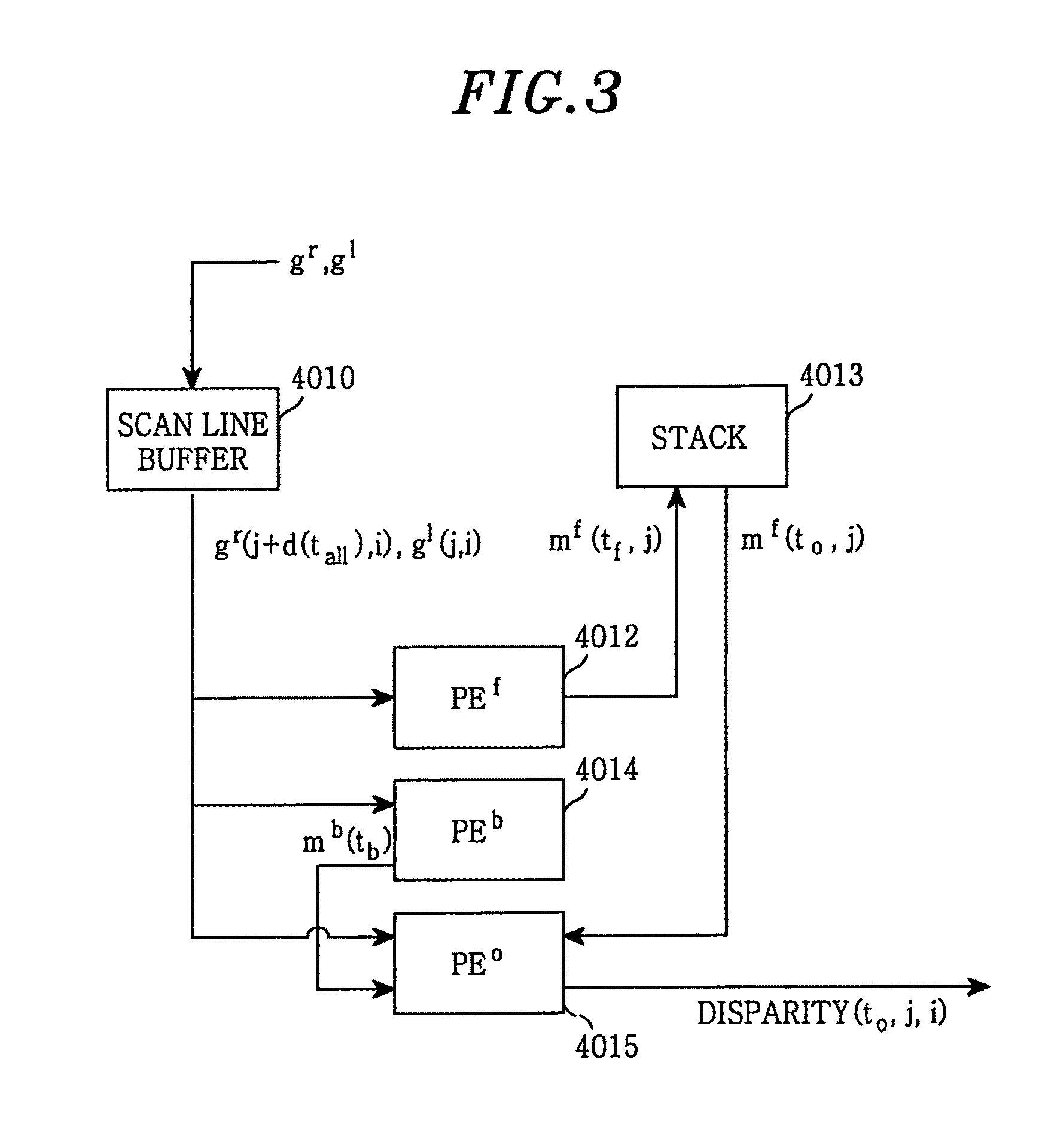
[0038]FIG. 3 is a block diagram of an image matching unit 40 for performing an algorithm I in accordance with the present invention.

[0039]Right and left side pixel data gr(j+d(tall),i) and g1(j,i) are stored in a scan line buffer 4011. Further, a forward processor PEf 4012 receives the right and the left side image pixel data, and stores a message mf(tf,j) computed by using the image pixel data values in a stack 4013. When a backward processor PEb 4014 also receives the right and the left side image pixel data gr(j+d(tall),i) and g1(j,i), and sends a message mb(tb) computed by using the image pixel data to a disparity computation processor PEo 4015, the disparity computation processor PEo 4015 receives the forward message mf(tf,j) stored in the stack 4013 from the stack 4013, the backward message mb(tb) and the right and the left side image pixel data, and thus outputs a disparity value.

second embodiment

[0040]FIG. 4 is a block diagram of an image matching unit 40 for performing an algorithm II in accordance with the present invention.

[0041]Right and left side image pixel data gr(j+d(tall),i) and g1(j,i) are stored in a scan line buffer 4021. A forward processor PEf 4022 receives the right and the left side image pixel data from the scan line buffer 4021, a downward message md(tall,j,i−1) computed for an upper line from a buffer 4026, and stores a forward message mf(tf,j) computed by using the received image pixel data and downward message in a stack 4023. When a backward processor PEb 4024 also receives the right and the left side image pixel data gr(j+d(tall),i) and g1(j,i) and the downward message md(tall,j,i−1), and sends a backward message mb(tb) computed by using the image pixel data and the downward message to a disparity computation processor PEo 4025, the disparity computation processor PEo 4025 receives the forward message mf(tf,j) from the stack 4023, the backward message...


PUM


Abstract

A stereo image matching system includes an image processing unit for converting input images inputted from a first and a second image acquisition unit into digital signals to output first and second pixel data; and an image matching unit for computing at least two of an upward, a downward, a forward and a backward message of each pixel by using data values of the first and the second pixel data that are located on a same epipolar line to calculate a disparity value of each pixel by using the computed messages corresponding to adjacent pixel(s). The stereo image matching system employs a parallel pipeline VLSI configuration with a time complexity of O(N). Thus, a plurality of image lines are used for matching, so that correct distance image information is obtained regardless of the conditions of the surrounding environment.

Description

TECHNICAL FIELD[0001]The present invention relates to a message propagation-based stereo image matching system and, more particularly, to a message propagation-based real-time parallel stereo matching system, which uses a multi-line or full image line processing method.BACKGROUND ART[0002]As well known to those skilled in the art, stereo matching is a method of reconstructing three-dimensional spatial information from a pair of two-dimensional images. As shown in FIG. 1, stereo matching is a method of detecting a left and a right side pixel corresponding to a specific location (X, Y, Z) in three-dimensional space from image lines of epipolar lines on a right and a left side image, respectively. The disparity d between a pair of the corresponding pixels is defined by the equation d=xr−x1.[0003]The disparity conveys distance information, and the gecmetrical characteristic referred to as a “depth” can be calculated therefrom. Therefore, if the disparity is calculated from input images ...

Claims


Application Information

Patent Timeline
Patent Type & Authority Patents(United States)
IPC IPC(8): H04N15/00G06V10/24
CPCG06K9/32G06T7/0075H04N13/0003G06T7/593H04N13/10G06V10/24
Inventor JEONG, HONGPARK, SUNG CHAN
Owner POSTECH ACAD IND FOUND
Why Eureka
Try Eureka