Rotatable valve in a cylinder intake duct

a technology of cylinder intake duct and rotating valve, which is applied in the direction of oscillatory slide valve, mechanical equipment, machines/engines, etc., can solve the problems of extremely limited available space in such regions and unnecessarily reduce the velocity of air, so as to improve air and fuel mixing, improve combustion stability, and increase combustion burn rate

Active Publication Date: 2013-04-30
FORD GLOBAL TECH LLC
View PDF26 Cites 8 Cited by
  • Summary
  • Abstract
  • Description
  • Claims
  • Application Information

AI Technical Summary

Benefits of technology

[0002]Vehicles with direct injection engines employ various methods for mixing fuel and air in an engine cylinder. Efficient mixing increases combustion burn rate, improving combustion stability and knock suppression. Spark ignition engines may use tumble flow motion to generate turbulence, which includes rotational motion generally perpendicular to the cylinder axis to improve air and fuel mixing. Depending on operating conditions, more or less tumble flow may be advantageous.
[0005]Thus, some of the above issues may be at least partly addressed by an engine cylinder head coupled to a cylinder, comprising an intake duct having a wall, and a rotatable valve, wherein a cross-section of the valve has a first surface with greater curvature than a second surface. In a first position, the second surface aligns with a curve in the wall, and in a second position, the first surface and the second surface protrude into the duct and form a step at the wall. In one example, the first position allows airflow through the intake duct with a reduced obstruction, since the second surface aligns with the curved wall of the intake duct. This first position of the valve may be used during high load / speed in an engine to increase airflow efficiency, and thus increase peak torque of the engine. In the second position, the first surface and the second surface may create a downstream step in the intake duct via their protrusion into the duct, which can increase tumble flow patterns in the intake air and cylinder. Thus, the second position may be used during low engine load / speed to increase the tumble flow. Further, because the valve can rotate between these positions, as well as potentially other positions therebetween or thereafter, a compact engine cylinder head design is achieved.

Problems solved by technology

Such an approach may create significant flow resistance and unnecessarily reduce the velocity of air as it travels from the intake side of the slide plate to the cylinder side of the slide plate.
In compact engine designs, the available space in such regions is extremely limited.

Method used


Image

  • Rotatable valve in a cylinder intake duct
  • Rotatable valve in a cylinder intake duct
  • Rotatable valve in a cylinder intake duct

Examples


Embodiment Construction

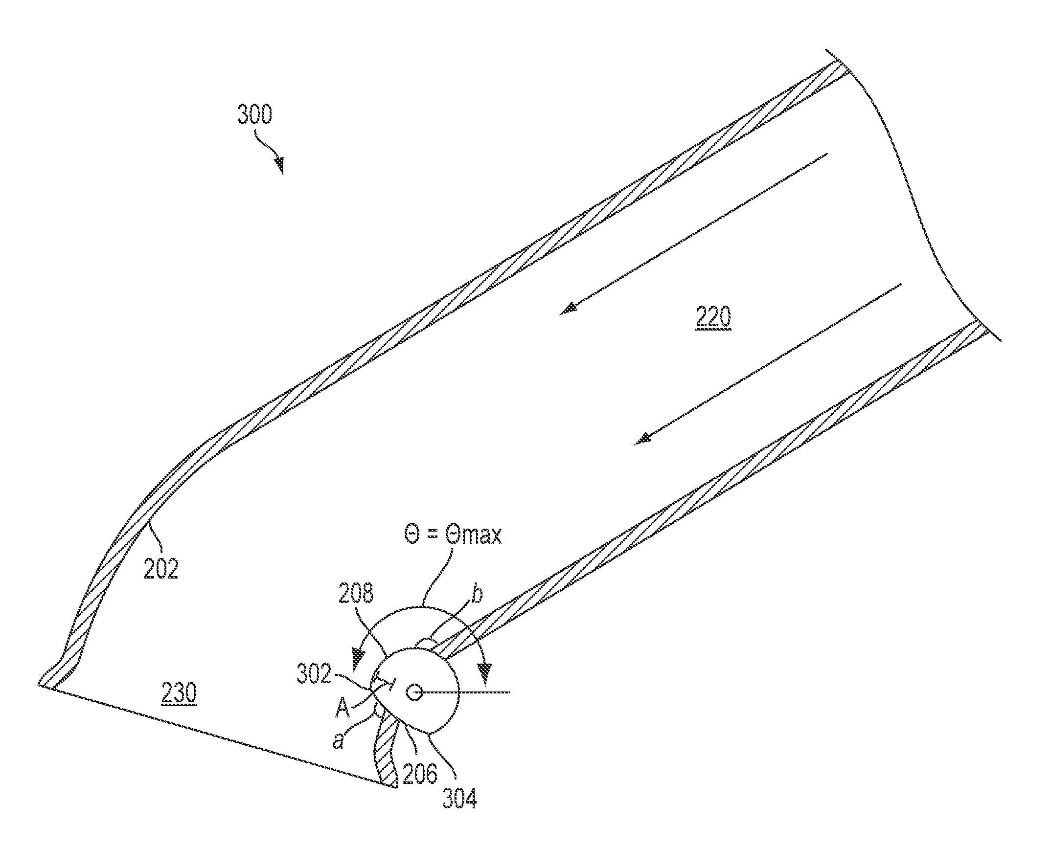
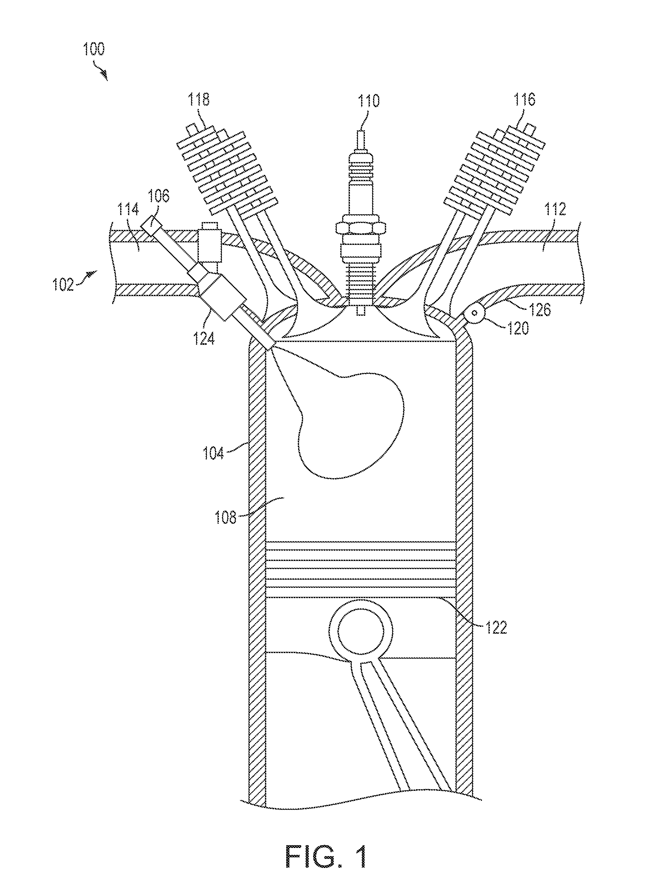
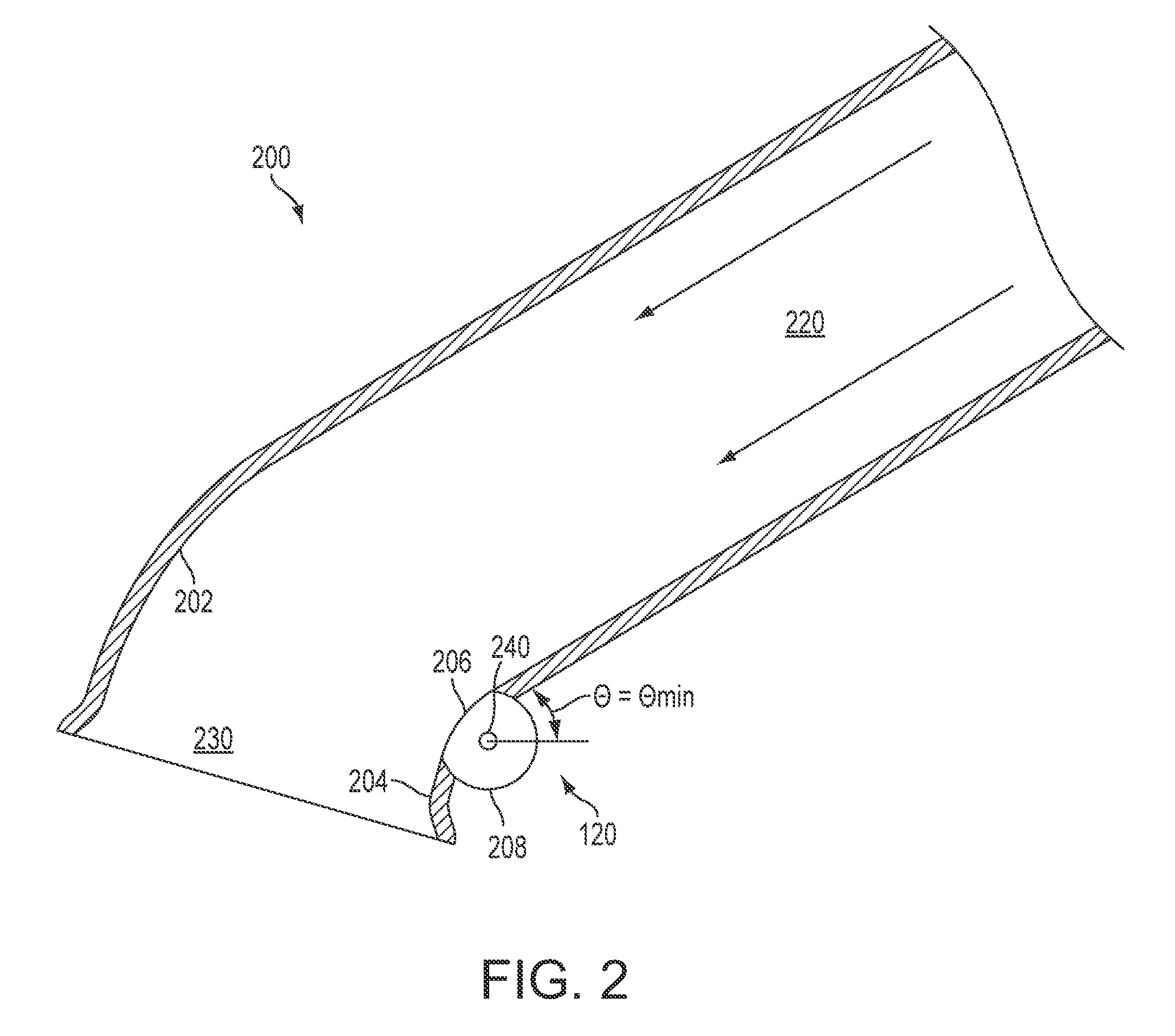
[0015]The following description relates to a cylinder head including an intake duct with a rotatable valve for an engine of a vehicle, such as a spark ignition direct injection gasoline engine. Spark ignition engines may use tumble flow motion to generate turbulence in fuel cylinders, which includes rotational motion generally perpendicular to the cylinder axis, wherein the angular velocity is proportional to the engine speed. A tumble ratio is defined as the angular velocity normalized by the engine speed. Thus, tumble ratio can be used to represent the strength of the in-cylinder airflow motion. When a tumble ratio is low, the tumble airflow motion may be insufficient to provide turbulence for efficient mixing of air and fuel, resulting in engine performance degradation. In order to provide efficient mixing of air and gas in a cylinder of an engine, which is operated at both high and low load / speed, the rotatable valve in the intake duct may be rotated between a first position (at...


PUM


Abstract

A spark ignition direct injection fuel cylinder for an engine includes a rotatable valve at a curved wall of an intake duct. The rotatable valve provides a variable step in to adjust the degree of tumble airflow while reducing flow restriction to improve engine performance across operating conditions.

Description

FIELD[0001]The present application relates to a method and a system for regulating a tumble airflow pattern in an engine cylinder for a vehicle, such as a spark ignition direct injection cylinder, via a rotatable valve in an air intake duct.BACKGROUND AND SUMMARY[0002]Vehicles with direct injection engines employ various methods for mixing fuel and air in an engine cylinder. Efficient mixing increases combustion burn rate, improving combustion stability and knock suppression. Spark ignition engines may use tumble flow motion to generate turbulence, which includes rotational motion generally perpendicular to the cylinder axis to improve air and fuel mixing. Depending on operating conditions, more or less tumble flow may be advantageous.[0003]U.S. Pat. No. 5,718,198 provides one example approach to regulate tumble flow using a slide plate midway through each of a plurality of intake runners. The slide plate includes a plurality of holes with a size and shape complementary to those of ...

Claims


Application Information

Patent Timeline
Patent Type & Authority Patents(United States)
IPC IPC(8): F02B31/06
CPCF02B31/085F02B2023/106Y02T10/146Y02T10/12
Inventor MCCARTHY, THOMAS A.YI, JIANWEN JAMES
Owner FORD GLOBAL TECH LLC
Why Eureka
Try Eureka