
Downhill vehicle speed control algorithm for electric driven vehicles

a technology of electric driven vehicles and speed control algorithms, which is applied in the direction of motor/generator/converter stoppers, dynamo-electric converter control, transportation and packaging, etc., can solve the problems of reducing the durability of the stack, reducing the dynamic power of the fuel cell system for the vehicle, and reducing the time delay from system start-up to driveability and low acceleration of the vehicl

Inactive Publication Date: 2013-04-30
GM GLOBAL TECH OPERATIONS LLC
View PDF6 Cites 36 Cited by
  • Summary
  • Abstract
  • Description
  • Claims
  • Application Information

AI Technical Summary

Benefits of technology

The present invention is a control system for electric vehicles that prevents them from driving too fast on downhill gradients by using regenerative braking. The system receives an enable signal if certain conditions are met and a vehicle speed signal. The system then controls the vehicle to speed up or down to a set-point based on the vehicle speed. If the vehicle speed exceeds the set-point, the system will output a regenerative braking torque command to the motor to reduce the speed of the vehicle. This system ensures safer and efficient driving of electric vehicles on downhill gradients.

Problems solved by technology

The dynamic power of a fuel cell system for a vehicle is limited.
Further, the time delay from system start-up to driveability and low acceleration of the vehicle may not be acceptable.
The voltage cycles can decrease the stack durability.
However, vehicle acceleration may require 100 kW or more of power.
The vehicle operator can apply brake pressure to the brake pedal to maintain the speed of the vehicle relatively constant as it is going downhill, but the brakes may become overheated as a result of the braking required to reduce the vehicle speed.
However, it would generally be difficult to use the braking torque of the engine to provide a constant speed when going downhill, because it requires the vehicle operator to continuously be providing gear shifts and brake applications.

Method used


Image

  • Downhill vehicle speed control algorithm for electric driven vehicles
  • Downhill vehicle speed control algorithm for electric driven vehicles
  • Downhill vehicle speed control algorithm for electric driven vehicles

Examples


Embodiment Construction

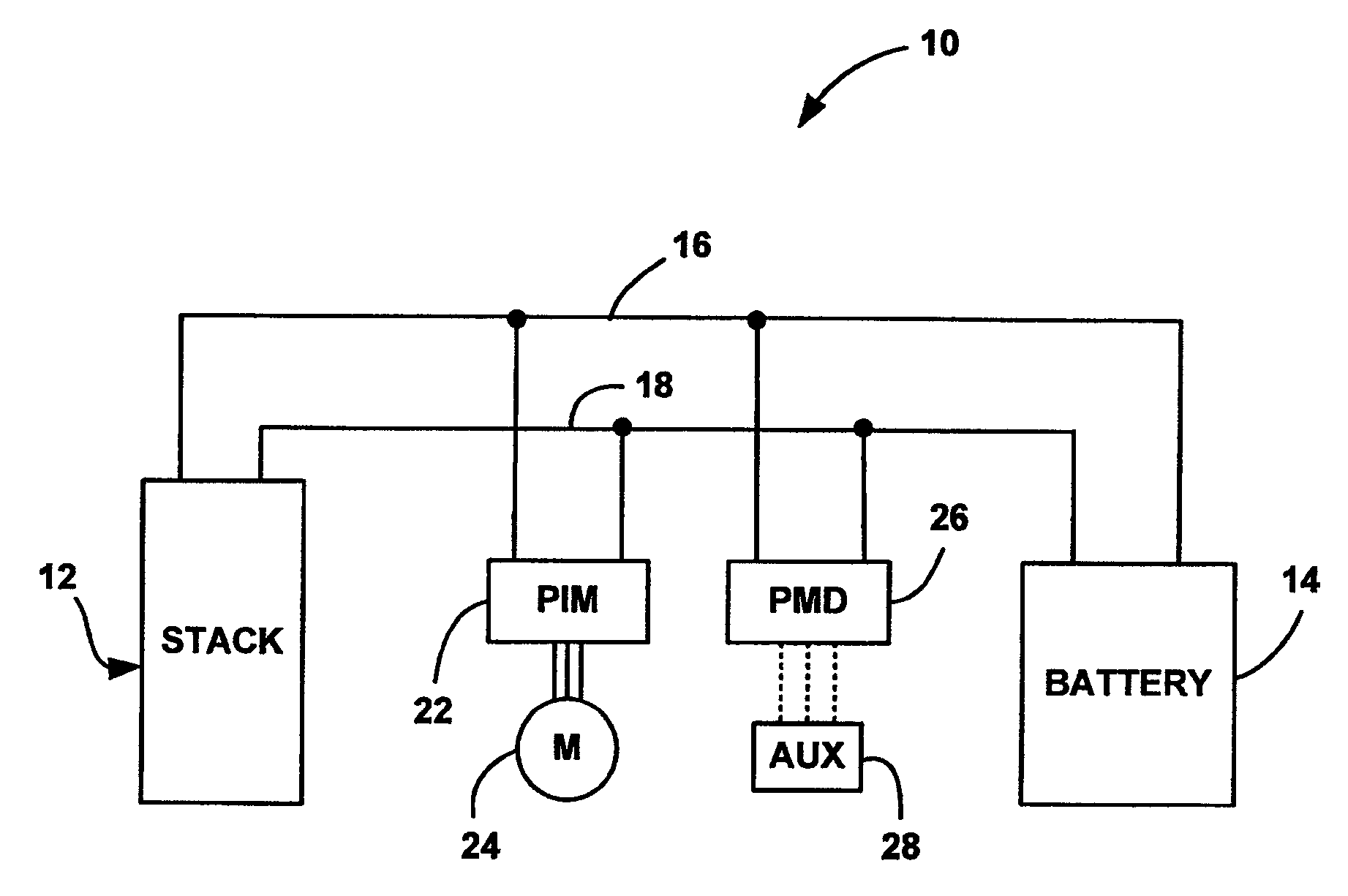
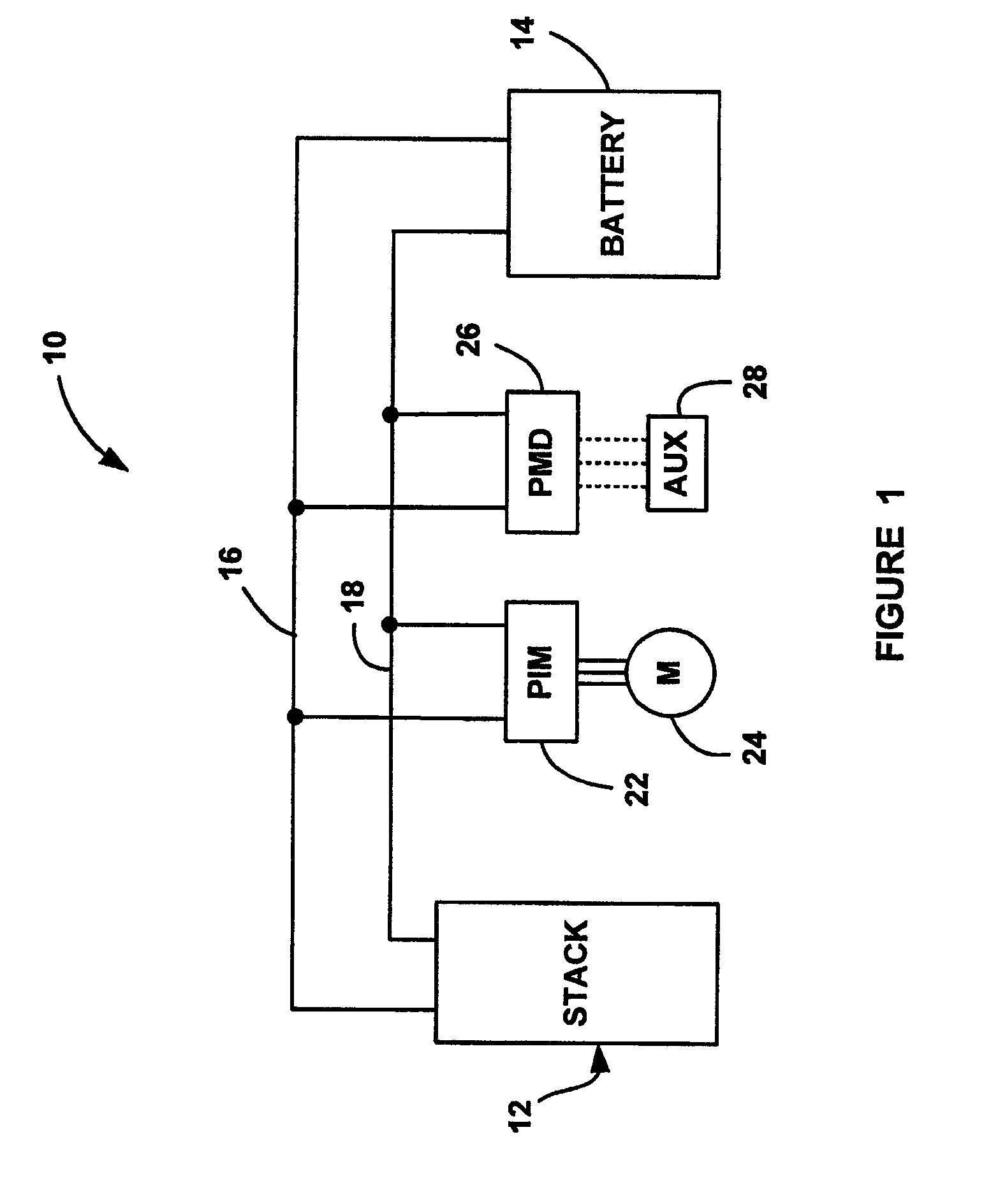
[0013]The following discussion of the embodiments of the invention directed to a control algorithm for controlling the speed of an electrical vehicle on a downhill gradient is merely exemplary in nature, and is in no way intended to limit the invention or its applications or uses. For example, the control algorithm of the present invention has particular application for a fuel cell vehicle employing a battery and an electrical traction system. However, as will be appreciated by those skilled in the art, the present invention also has application for any type of electrically driven vehicle, including an internal combustion hybrid vehicle.

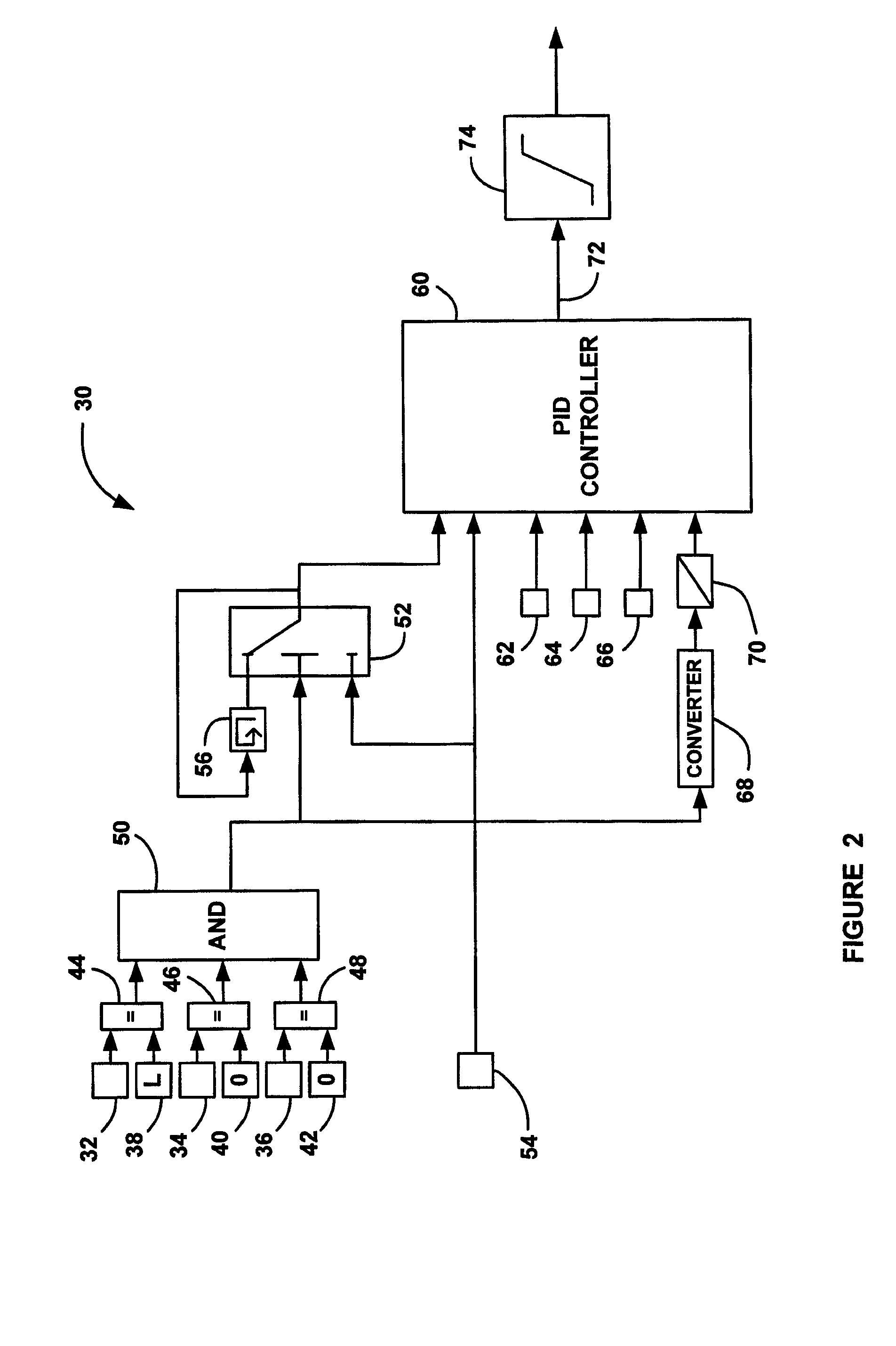
[0014]FIG. 2 is a block diagram of a control system 30 for controlling the speed of an electrically driven vehicle traveling downhill. The position of the shifter of the vehicle is provided at node 32, the position of the acceleration pedal of the vehicle is provided at node 34 and the position of the brake pedal of the vehicle is provided at node 36...


PUM


Abstract

A control system that prevents an electric vehicle from increasing its speed on a downhill gradient by providing regenerative braking through a traction motor. The system includes an enable circuit that provides an enable signal if certain criteria are met, such as a brake pedal and an acceleration pedal being inactive. The system further includes a controller that is enabled by the enable signal, and receives a vehicle speed signal of the speed of the vehicle. The system also includes a switch that receives the enable signal and the vehicle speed signal. When the enable circuit provides the enable signal, the switch provides a speed set-point to the controller for the last vehicle speed. If the vehicle speed signal goes above the speed set-point, the controller outputs a regenerative braking torque command to the traction motor to reduce the speed of the vehicle to the speed set-point.

Description

BACKGROUND OF THE INVENTION[0001]1. Field of the Invention[0002]This invention relates generally to a method for controlling the speed of an electrically driven vehicle and, more particularly, to a method for controlling the downhill speed of an electrically driven vehicle that prevents the vehicle speed from increasing beyond a speed set-point by using regenerative braking.[0003]2. Discussion of the Related Art[0004]The dynamic power of a fuel cell system for a vehicle is limited. Further, the time delay from system start-up to driveability and low acceleration of the vehicle may not be acceptable. During a drive cycle, the stack fuel cell voltages vary because the variable driver power request follows the stack polarization curve. The voltage cycles can decrease the stack durability. These drawbacks can be minimized by using a high voltage battery in parallel with the fuel cell stack. Algorithms are employed to provide the distribution of power from the battery and the fuel cell s...

Claims


Application Information

Patent Timeline
Patent Type & Authority Patents(United States)
IPC IPC(8): B60W10/18B60W30/18
CPCB60K31/04B60L15/2009B60L2210/20B60W10/18B60W30/18127Y10T477/373B60W2550/142B60W2710/18Y02T10/725Y02T10/7275Y10T477/363B60W2050/0011B60W2552/15Y02T10/64Y02T10/72B60W30/146
Inventor NOLL, MARKUS
Owner GM GLOBAL TECH OPERATIONS LLC
Learn More