When the part is stressed, the brittle
lacquer cracks, starting at the areas of highest strain.
As such, the brittle lacquer method can only indicate which areas of a part are experiencing stress and strain.
Also, only one test is possible with a given application of brittle lacquer.
Ifju's coating is luminescent and changes in strain cause cracks that can be seen because of the different properties in how the coating luminesces.
The problem with this type of coating as with all brittle coatings is they are difficult to apply and use.
Only one test is possible and the brittle coatings are typically not suitable for use in production parts and structural monitoring applications where environmental and
corrosion protection are required.
Because of the disadvantages and the complexity of strain gages, brittle lacquer, and
fiber-
optics, these techniques for measuring stress and strain are typically used only at the product development stage for high-value products such as aircraft parts.
Existing techniques of detecting stress and strain are expensive enough to make them somewhat prohibitive even on prototypes at the product development stage.
However, existing NDT techniques are typically expensive to apply and cannot detect certain types of failure such as plastic deformation and some structural overloading that does not result in cracks.
NDT techniques described can typically detect voids or cracks, but cannot typically detect whether a
structural component has been subjected to a stress that is too high, or whether it has experienced any plastic deformation.
Structures such as buildings, bridges, airplanes,
industrial equipment and other critical structures are prone to failure.
Failure can happen with significant
loss of life and property, as evidenced by the recent collapse of the I-35 bridge in Minnesota.
As this infrastructure further ages and the concern for public safety increases, structural monitoring will become more and more critical.
However, budgets for carrying out inspections of public structures such as bridges are very low.
Prior art approaches to structural monitoring are typically too expensive, impractical, and / or insufficient for addressing the growing need for structural monitoring, particularly the structural monitoring of bridges.
Prior art approaches to structural monitoring typically involve expensive monitoring devices and expensive monitoring systems.
These factors combine to make this
system expensive and less suitable for large scale deployment for structural monitoring.
While this approach can give an accurate
time history of stresses experienced by a structure, it can be prohibitively expensive because of the use of on-board monitoring and storage.
The collection of all the historical stress data can be inefficient and unnecessary.
The regular storage and retrieval of all the data can be very expensive and can require frequent visits to perform downloads.
Also, because data will only be recorded at a certain sampling rate, it is possible with Brennen'
s system to miss key events such as stress strain peaks.
This could lead to false conclusions regarding the safety of the structure because key peak events have been missed.
Reducing the sampling rate in order to reduce the amount of data stored only makes the problem of missing key events worse.
This method however can only detect cracks, and the requirement of microcapsules containing coloured dyes can make the method difficult and expensive.
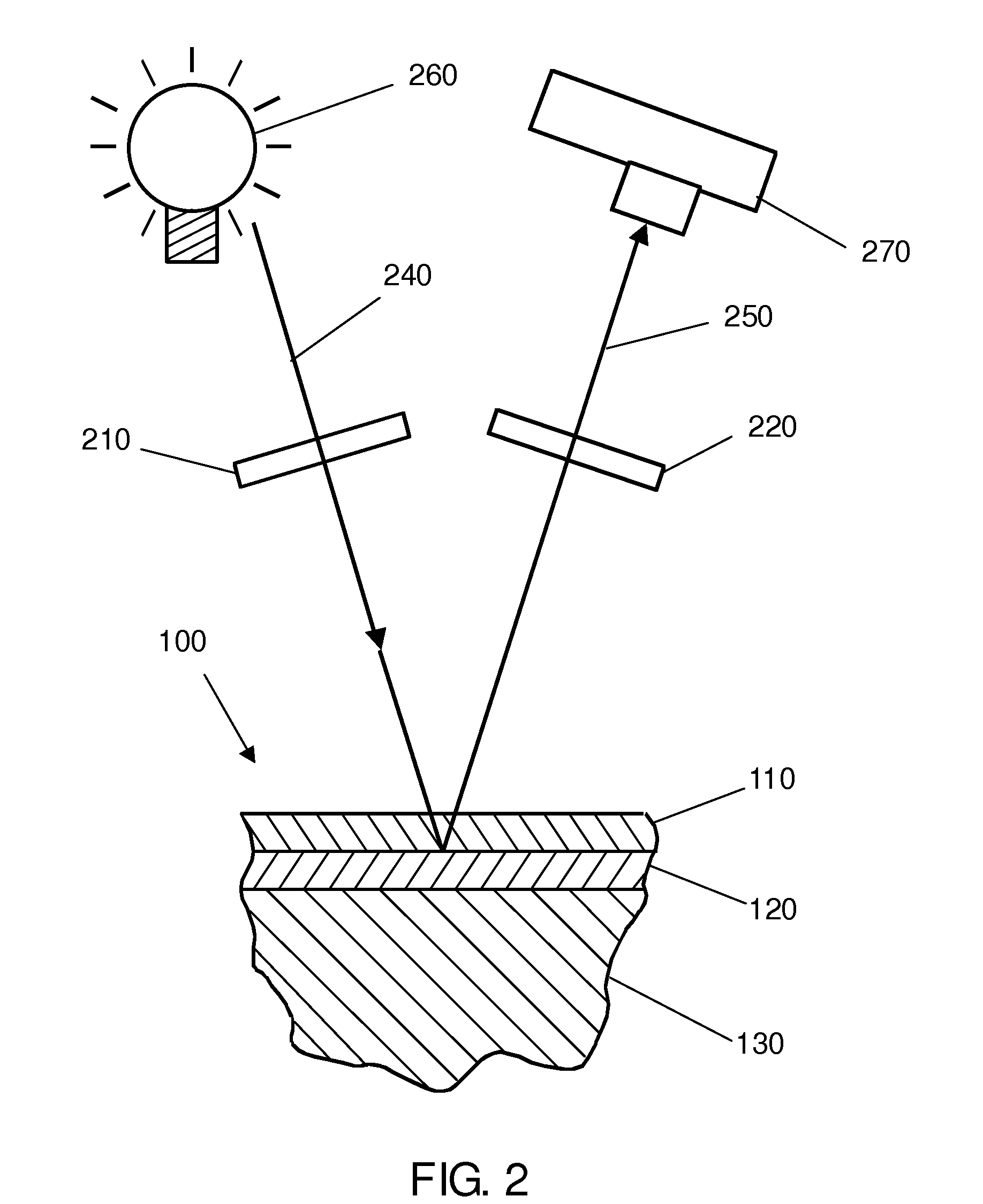
The photoelastic effect is caused by alternately constructive and destructive interference between light rays that have undergone relative retardation, or phase shift, in the stressed photoelastic material.
Photoelastic coatings have traditionally only been used for
laboratory testing or prototype testing because of the cost of the coatings, the difficulty of applying the coatings, and the unsuitability of the coatings for production components or for applying to structures in the field.
Both these types of coatings can be cost and labour-intensive to apply, and are not well suited for complex parts, large parts, or parts made in higher quantities.
However, the method of applying a photoelastic coating techniques as disclosed by Lam and Ellens in U.S. Pat. No. 6,650,405 suffers from a number of limitations.
For example, applying a photoelastic coating with
powder coating is limited in its applicability to structural monitoring of larger structures such as bridges, buildings, and larger
aerospace components, particularly in the field.
One limitation is that
powder coating is applied as a dry finely-divided
solid powder and typically needs to be baked on by increasing the temperature of the powder and the part being coated to an
elevated level (typically from 100° C. to 200° C.).
This can be impractical or inconvenient for large parts such as bridge trusses and large beams because these parts may not fit into an oven, and also because the energy required to heat these parts up to the temperature required can be prohibitive and energy inefficient.
It may also not be practical to apply
powder coating to some structures already in use, particularly if they are installed on a permanent basis in the field.
For example, some times of alloys are subjected to heat treatments that can be affected if the part is subsequently heated to an elevated temperature.
Applying a photoelastic layer to these parts using
powder coating may not be practical or possible.
However,
powder coating can be an impractical or inconvenient method for applying a photoelastic coating for a number of reasons:Difficulty of applying a powder coated photoelastic layer to structures already installed in the fieldDifficulty of applying a powder coated photoelastic layer to large structures such as bridges and buildings.Power coating can typically only be applied to materials that can carry an
electric charge such as metals.Applying a powder coated photoelastic layer to a large structure with significant
thermal mass requires too much energy to heat up the structure to fuse the powder coating together.Some materials (e.g., some heat-trated alloys) cannot be subjected to the elevated temperatures required for baking and fusing the powder coated photoelastic layer together.

