Light irradiation device for recording information in a hologram recording medium

a technology of light irradiation and recording information, which is applied in the field of light irradiation device for recording information in a hologram recording medium, can solve the problems of increasing device manufacturing cost and correspondingly increasing device manufacturing cost, and achieve the effect of reducing device manufacturing cos

Inactive Publication Date: 2013-04-30
SONY CORP
View PDF6 Cites 4 Cited by
  • Summary
  • Abstract
  • Description
  • Claims
  • Application Information

AI Technical Summary

Benefits of technology

[0107]Thus, according to the above configuration, the amount of error from the ideal distance for the distance between the objective lens and the relay lens can be optically detected, and accordingly, positions sensors for detecting the position of each of the objective lens and the relay lens which have been unavoidable with the related art for control so that the distance between the objective lens and the relay lens remains constant, can be omitted. That is to say, thus, reduction in device manufacturing cost can be achieved.

Problems solved by technology

With such a control technique according to the related art, the position sensors 104 and 105 for detecting the positions of the objective lens 102 and the relay lens 7 have to be provided, which causes increase in device manufacturing cost correspondingly.
Also, such a control technique according to the related art is so-called open control, high precision is demanded for the reference positioning and attachment precision and the like of the position sensors, and accordingly, this point also causes increase in device manufacturing cost.

Method used


Image

  • Light irradiation device for recording information in a hologram recording medium
  • Light irradiation device for recording information in a hologram recording medium
  • Light irradiation device for recording information in a hologram recording medium

Examples


Embodiment Construction

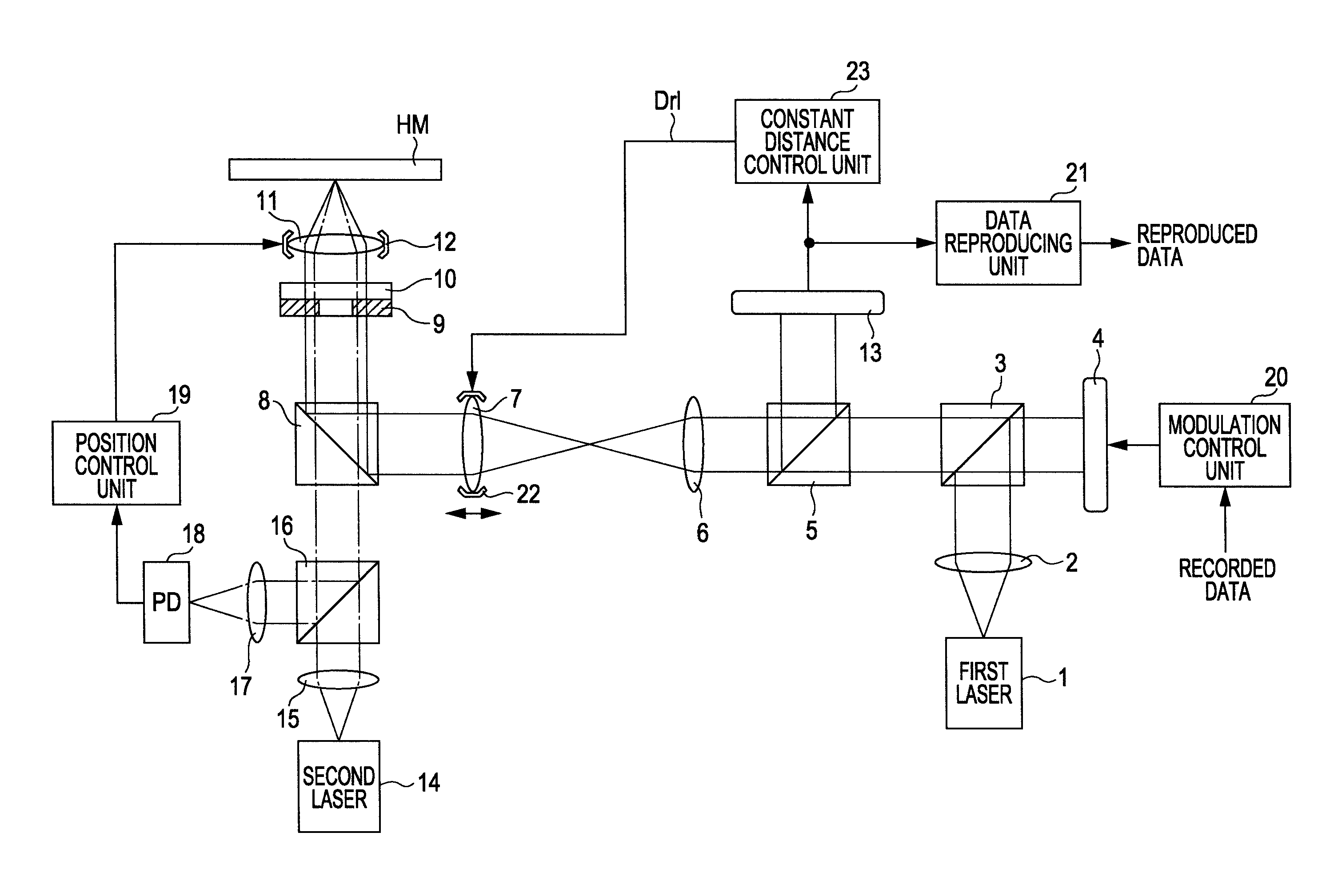
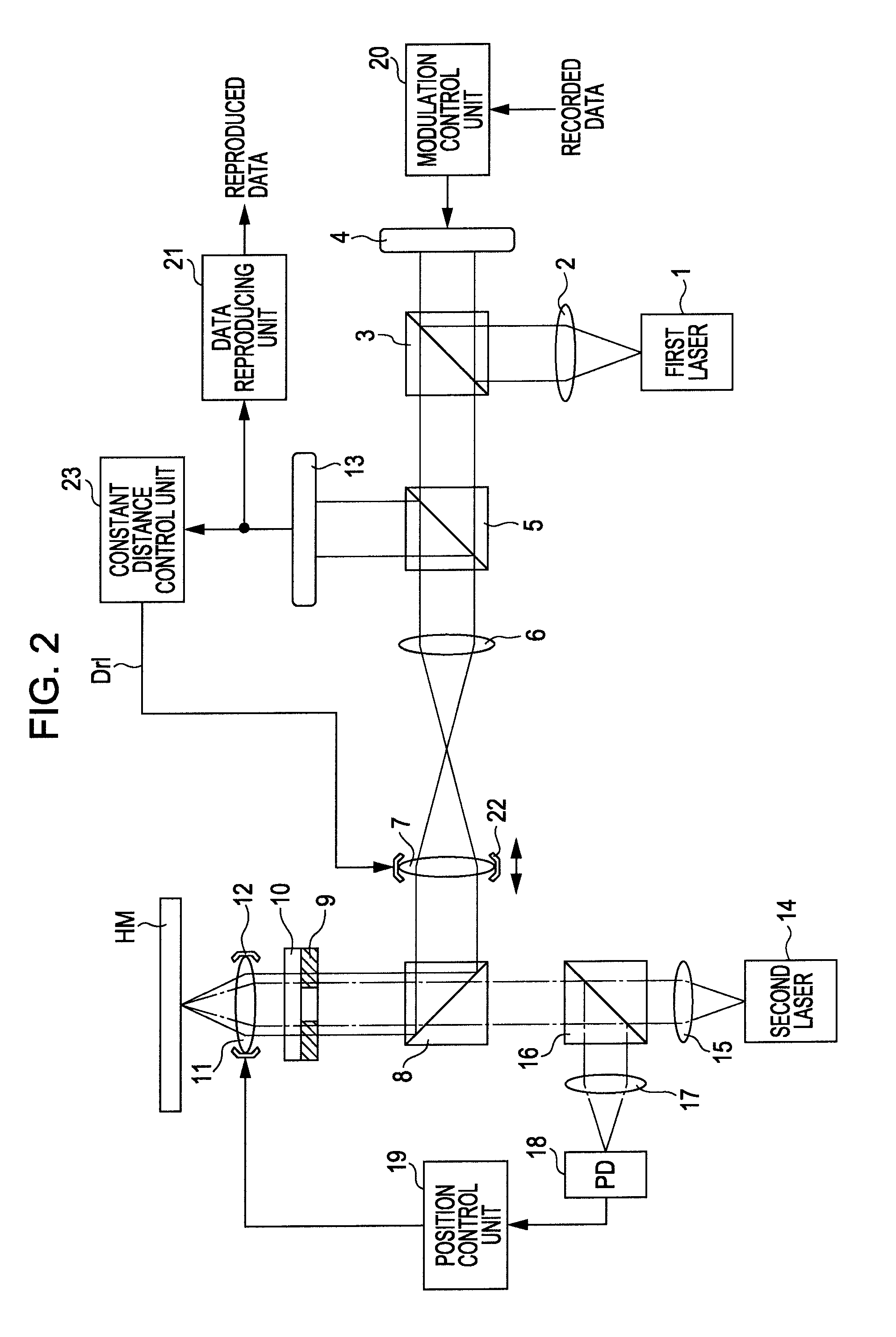
[0136]An embodiment for carrying out the present invention (hereafter, referred to as “embodiment”) will be described below. Description will be made in accordance with the following sequence.[0137]1. Configuration of Hologram Recording / Reproducing System[0138]1-1. Configuration of Recording Medium[0139]1-2. Configuration of Recording / Reproducing Device[0140]1-3. Shift of Focal Position[0141]1-4. Change of Behavior of Light Following Focal Position Shift[0142]1-5. Constant Distance Control between Objective Lens and Relay Lens Serving as Embodiment[0143]1-6. Configuration for Realizing Constant Distance Control of Embodiment[0144]1-7. Conclusion[0145]2. Modifications

1. Configuration of Hologram Recording / Reproducing System

1-1. Configuration of Recording Medium

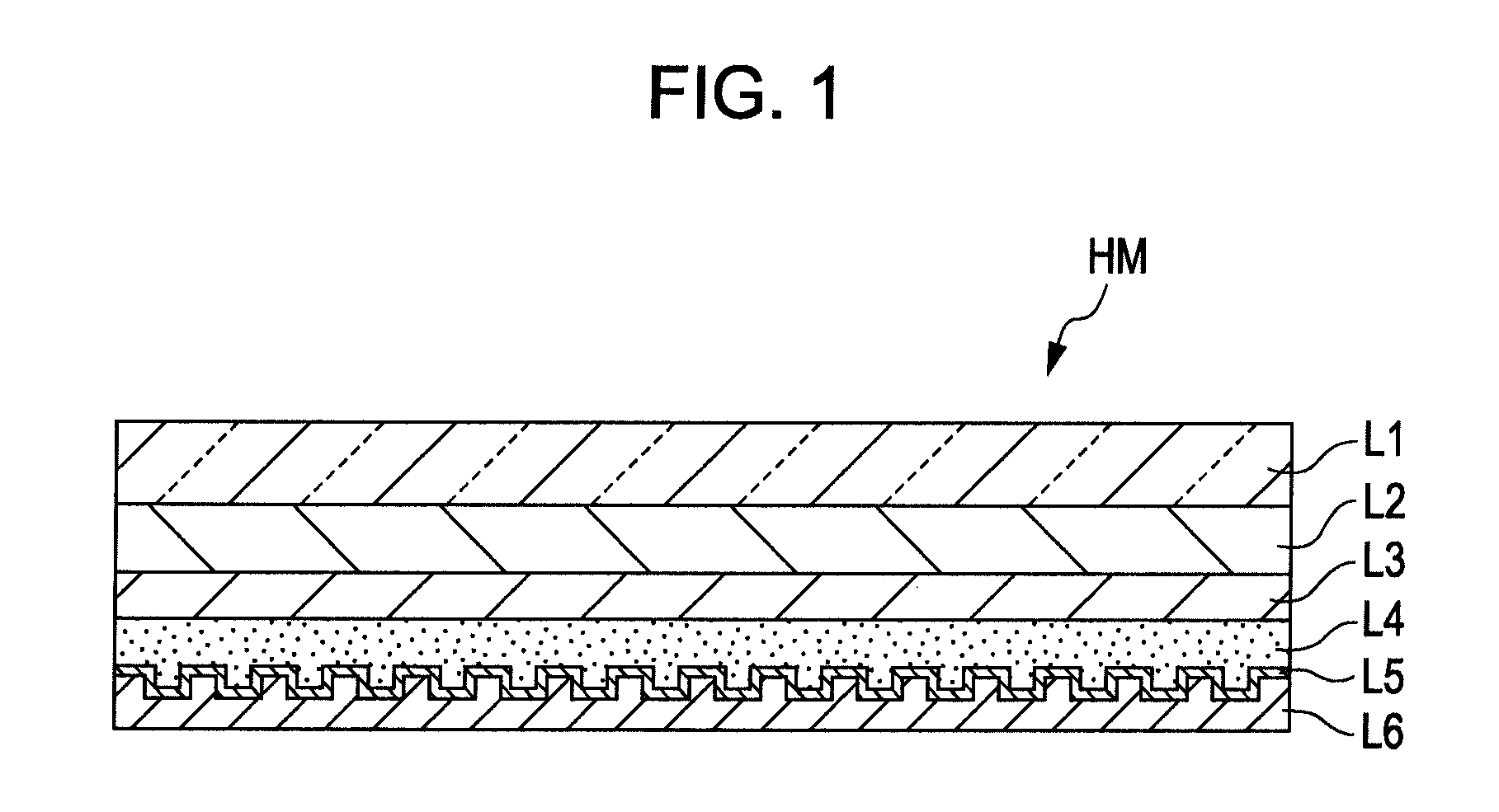
[0146]FIG. 1 is a cross-sectional configuration diagram of a hologram recording medium HM according to the present embodiment. As can be understood from comparison between this FIG. 1 and the previous FIG. 22, the hologram reco...


PUM


Abstract

A light irradiation device includes: a focus servo control unit including a light source, a spatial light modulating unit, and a light irradiating unit, for focus servo control so that the ideal focal position of light via an objective lens is such that distance between an ideal focal position and a hologram recording medium surface is smaller than distance from the surface to the lower layer side face of the recording layer, and the focal position of light via the objective lens is constant at the ideal focal position; an objective-lens / relay-lens distance adjusting unit to adjust distance between the objective lens and a relay lens close to the objective lens; a light reception unit to receive marker light; and a constant distance control unit to control the objective-lens / relay-lens distance adjusting unit based on error between the ideal position of the marker light, and the actual position of the marker light.

Description

[0001]The present application contains subject matter related to that disclosed in Japanese Priority Patent Application JP 2009-078995 filed in the Japan Patent Office on Mar. 27, 2009, the entire content of which is hereby incorporated by reference.BACKGROUND OF THE INVENTION[0002]1. Field of the Invention[0003]The present invention specifically relates to, of light irradiation devices which irradiate light on a hologram recording medium, a light irradiation device including a mechanism for adjusting distance between an objective lens and a relay lens, and also relates to a control method for controlling the distance between the objective lens and the relay lens so as to be constant.[0004]2. Description of the Related Art[0005]The hologram recording / reproducing method for executing recording of data using a hologram format has been in practical use, as disclosed in Japanese Unexamined Patent Application Publication No. 2007-79438 for example. With the hologram recording / reproducing...

Claims


Application Information

Patent Timeline
Patent Type & Authority Patents(United States)
IPC IPC(8): G03H1/04
CPCG11B7/0908G11B7/1275G11B7/128G11B7/1374G11B7/1378G11B7/083G11B7/24038G11B7/24044G11B7/00781
Inventor YAMAKAWA, AKIOOKAMOTO, YOSHIKITANAKA, KENJITOKUYAMA, KAZUTATSUTAKASAKI, KOJI
Owner SONY CORP
Why Eureka
Try Eureka