Optical drive device and tilt detection method

a technology of optical drive and tilt detection, applied in the direction of digital signal error detection/correction, instruments, recording signal processing, etc., can solve the problem of device miniaturization disadvantage, and achieve the effect of reducing device manufacturing cos

Inactive Publication Date: 2011-04-28
SONY CORP
View PDF2 Cites 2 Cited by
  • Summary
  • Abstract
  • Description
  • Claims
  • Application Information

AI Technical Summary

Benefits of technology

[0052]As a result, according to the embodiment of the present invention, it is possible to reduce device manufacturing cost or realize device miniaturization, by reducing the number of parts as compared with the related art.

Problems solved by technology

Thus, it is disadvantageous in terms of device miniaturization.

Method used


Image

  • Optical drive device and tilt detection method
  • Optical drive device and tilt detection method
  • Optical drive device and tilt detection method

Examples


first embodiment

3. First Embodiment

Detection Correction of Spot Deviation Due to Tilt

[3-1. Method of Detecting Spot Deviation Amount Due to Tilt]

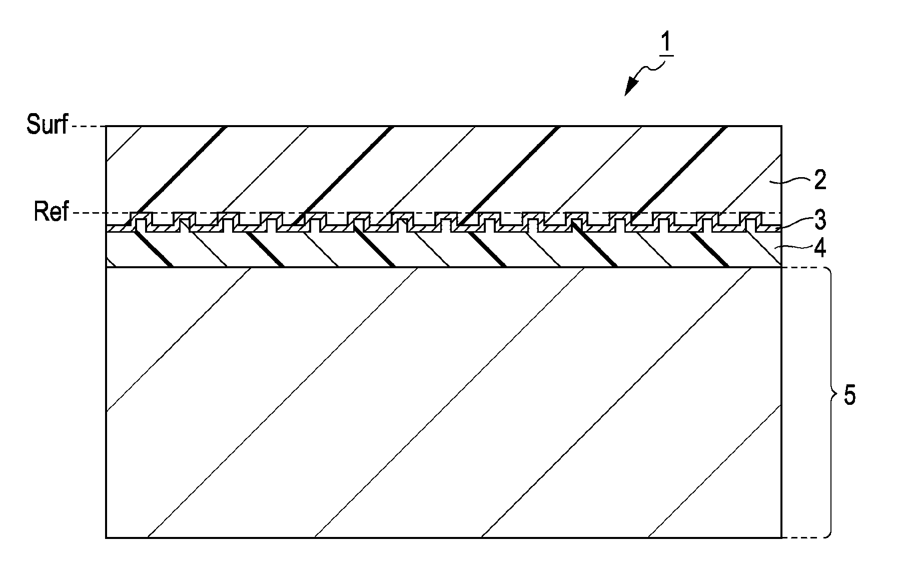
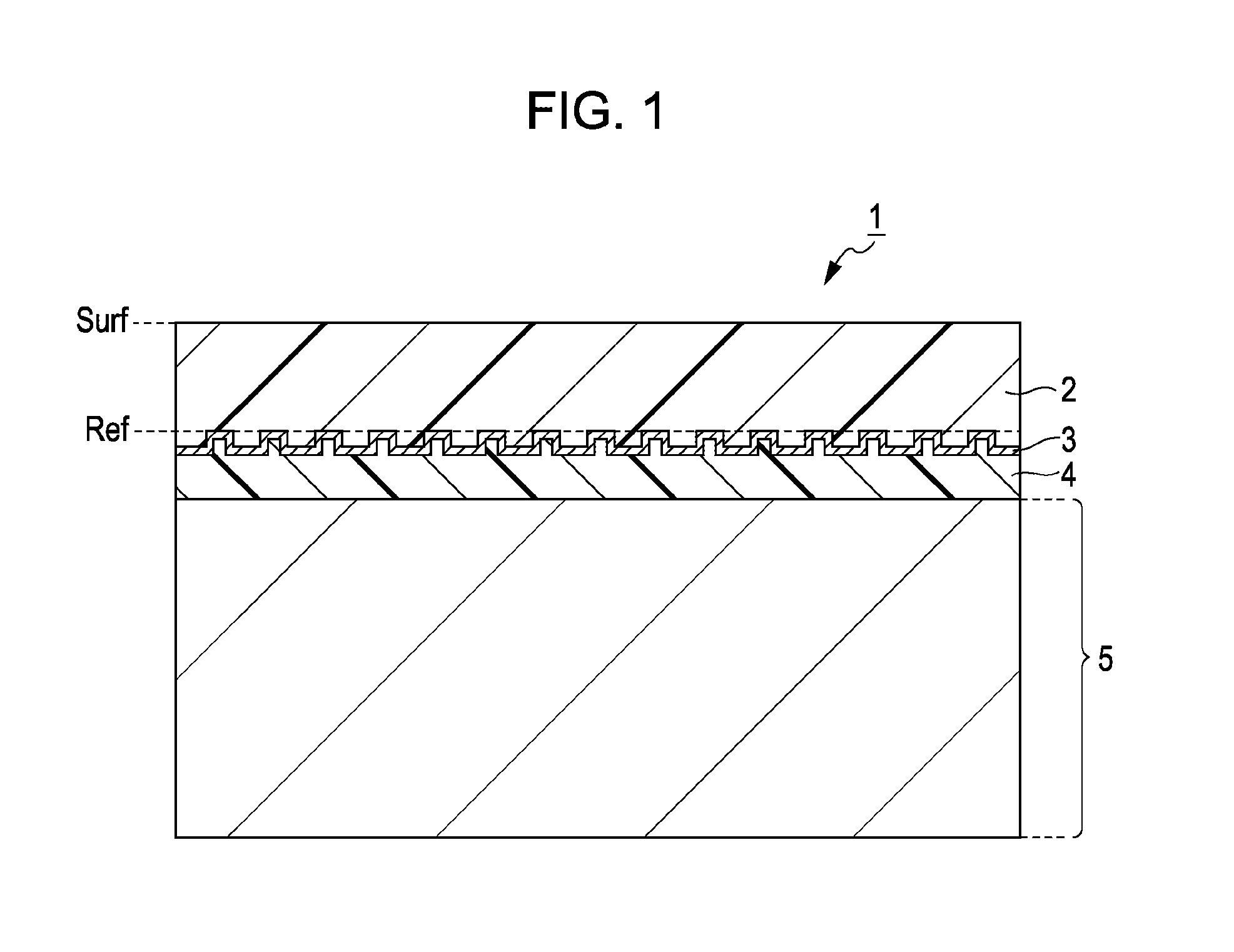
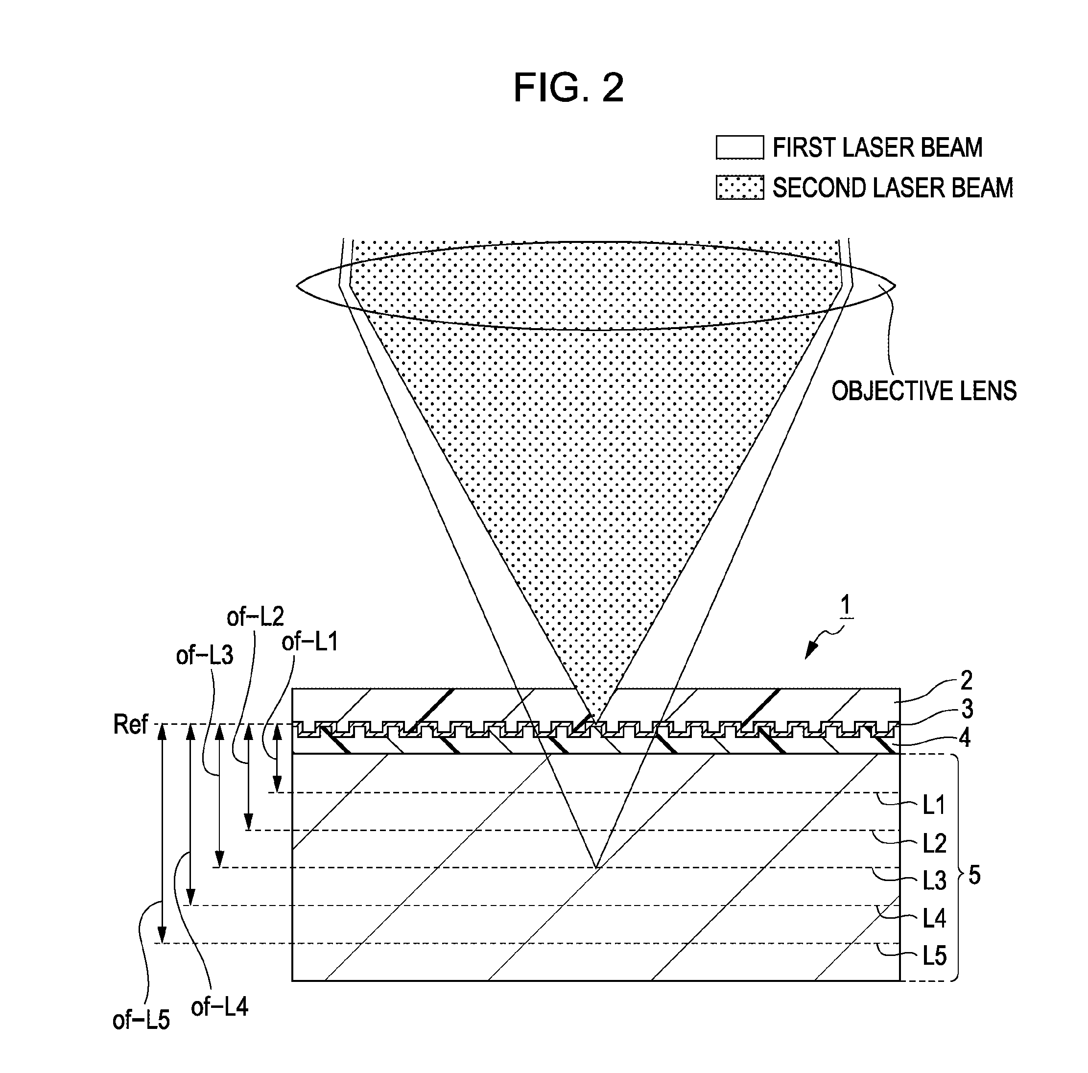
[0134]Here, as can be understood from the above description, in the present embodiment, in the bulk type recording medium 1, information recording or reproduction of recorded information is performed by formation of the mark by focusing the first light at the necessary position in the recording layer of the optical recording medium by the objective lens, and the second light is focused on the reflection film in which the position guide element of the optical recording medium is formed through the objective lens and the position of the objective lens is controlled such that the spot position of the second light follows the position guide element based on the reflected light of the second light focused on the reflection film.

[0135]As described above, in the case where the method of realizing the tracking servo control of the first laser beam by the tracking ...

second embodiment

4. Second Embodiment

Detection Correction of Spot Deviation Including Spot Deviation Due to Lens Shift

[4-1. Method of Detecting Spot Deviation Amount due to Lens Shift]

[0281]Subsequently, a second embodiment will be described. In the second embodiment, the detection and correction of the spot position deviation due to lens shift as well as tilt are performed.

[0282]Even in the second embodiment, only the tracking direction is considered with respect to the detection and correction of the spot position deviation amount.

[0283]As described in Japanese Unexamined Patent Application Publication No. 2008-310848, in the case where information recording or reproduction of recorded information by mark formation is performed by focusing a first light at a necessary position in a recording layer of an optical recording medium by an objective lens, a second light is focused on a reflection film, in which a position guide element of the optical recording medium is formed, through the objective len...


PUM

PropertyMeasurementUnit
angleaaaaaaaaaa
surface reflection light deviationaaaaaaaaaa
distanceaaaaaaaaaa

Abstract

An optical drive device for performing information recording or reproduction of recorded information by formation of a mark by focusing a first light at a necessary position in a recording layer of an optical recording medium by an objective lens includes a position control unit configured to focus a second light on a reflection film, in which a position guide element of the optical recording medium is formed, through the objective lens and to enable the spot position of the second light to follow the position guide element based on the reflected light of the second light focused on the reflection film so as to control the position of the objective lens. The optical drive device further includes a first focusing unit, a first light-sensing portion, and a surface reflection light deviation amount detection unit.

Description

BACKGROUND OF THE INVENTION[0001]1. Field of the Invention[0002]The present invention relates to an optical drive device for performing information recording or reproduction of recorded information by formation of a mark by focusing a first light at a necessary position in a recording layer of an optical recording medium by an objective lens and, more particularly, to an optical drive device for focusing a second light on a reflection film, in which a position guide element of the optical recording medium is formed, through the objective lens and enabling a spot position of the second light to follow the position guide element based on the reflected light of the second light focused on the reflection film so as to control the position of the objective lens, and a tilt detection method of such an optical drive device.[0003]2. Description of the Related Art[0004]As an optical recording medium for recording / reproducing a signal by irradiating a light, for example, a so-called optical d...

Claims


Application Information

Patent Timeline
Patent Type & Authority Applications(United States)
IPC IPC(8): G11B7/12
CPCG11B7/0065G11B2007/0013G11B7/0956
Inventor SAITO, KIMIHIROKUBO, TAKESHITANABE, NORIHIRO
Owner SONY CORP
Why Eureka
Try Eureka