
Water vapor separator and uniform heating pipe of jig dyeing machine heating system

A heating system and jigger technology, applied in the field of jigger heating system, can solve the problems of uneven dyeing of fabrics, uneven dyeing tank temperature, waste of steam, etc., to solve the problem of not being able to directly heat dyeing and reduce the workload of equipment maintenance , The effect of reducing equipment manufacturing costs

Inactive Publication Date: 2011-03-23
新建特阔漂整(南通)有限公司
View PDF0 Cites 3 Cited by
  • Summary
  • Abstract
  • Description
  • Claims
  • Application Information

AI Technical Summary

Problems solved by technology

However, at present, the heating system of dyeing jiggers produced at home and abroad is complicated, and the waste of steam and water is serious. There are four disadvantages when heating directly into the dyeing tank: First, the steam contains a large amount of water and is absorbed by the dyeing liquid, making the fabric easy to dry. Inhomogeneous dyeing occurs; the second is that the waste of water vapor with the insulation pipe is serious, it is always in the state of steam, no matter what the operator does, the insulation pipe is turned on, and the hot water flows into the sewer through the vegetable water valve; the third is direct heating , when heating from one end of the dyeing tank to the other, the size and pressure of the steam ejected from the steam pipe holes are different, resulting in uneven temperature around the dyeing tank, which will inevitably lead to uneven dyeing; It is impossible to ensure the temperature in the dyeing tank by using the temperature of the pipe. You can only open the air valve to add steam, and there is no way to solve the problem if there is water.

Method used


Image

  • Water vapor separator and uniform heating pipe of jig dyeing machine heating system
  • Water vapor separator and uniform heating pipe of jig dyeing machine heating system

Examples


Embodiment Construction

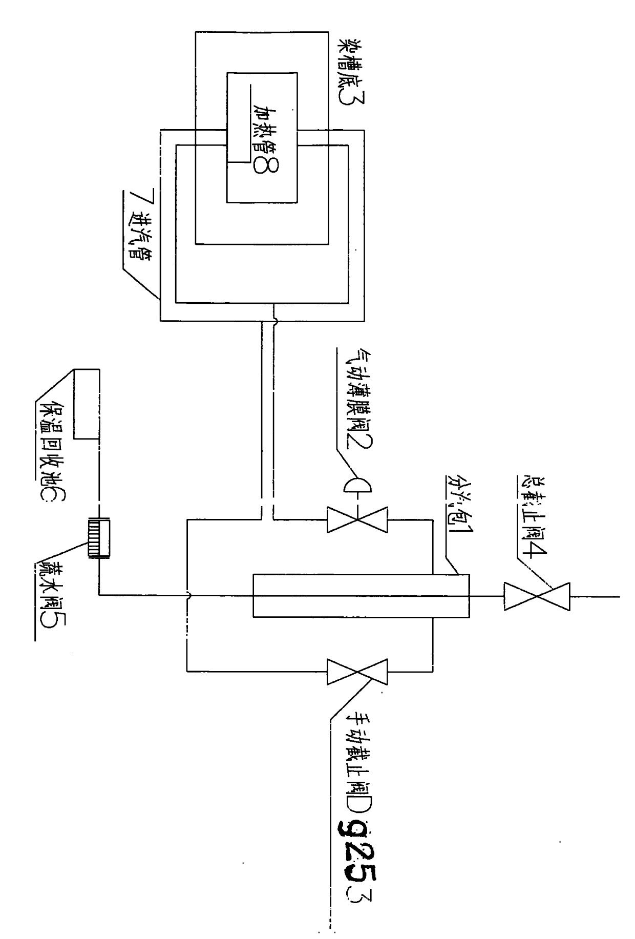
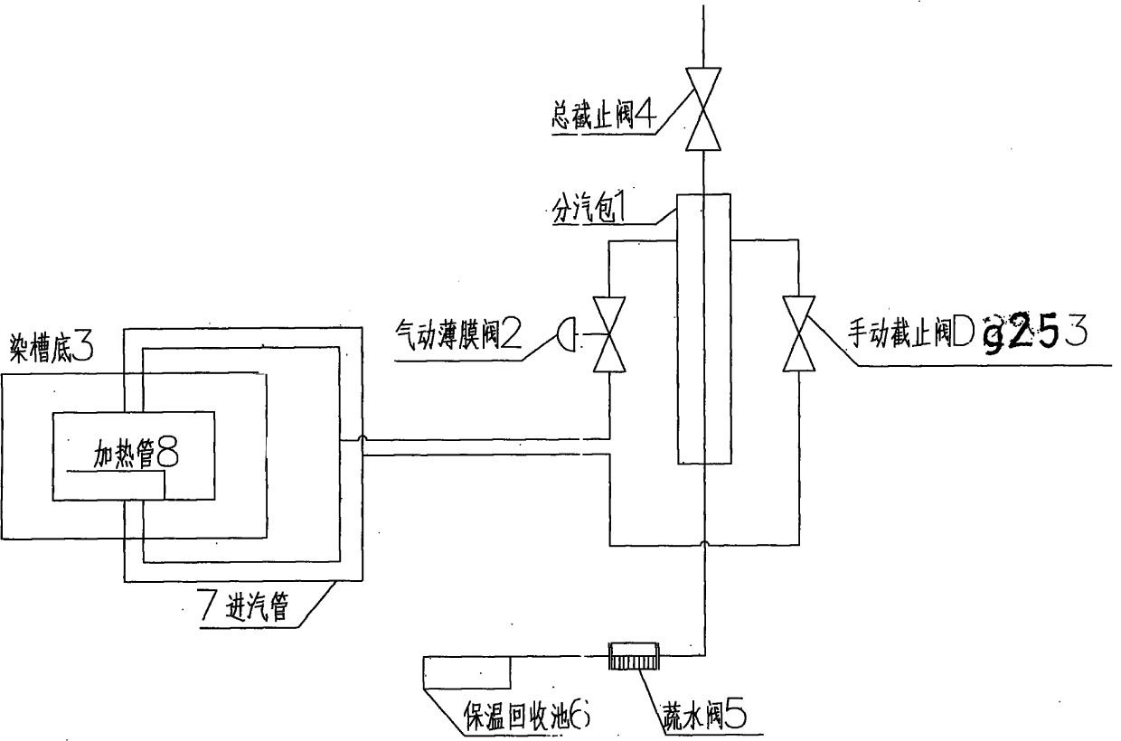
[0007] As shown in the figure, the present invention consists of a steam distribution drum 1, a total cut-off valve 4, a manual valve 3, an automatic pneumatic film valve 2, a steam inlet pipe 7, a heating pipe 8, a dyeing tank bottom 9, a vegetable water valve 5, heat preservation recovery The pool is composed of 6 and so on. The sub-steam drum 1 is composed of elbows, flanges, and pipes. It is assembled with a steam-operated membrane valve 2 and a manual stop valve 3 into automatic 2, manual 3, and valve control. The main stop valve 4 controls the steam source and 5 vegetable and water valves. The hot water is discharged to the thermal insulation recovery pool 6, and the steam inlet pipe 7 is temperature-controlled from the lower part of the dyeing tank 9 through the heating pipe in series.

[0008] The performance and characteristics comparison of the heating system of dyeing jigger

[0009] Dye Jigger Heating System

[0010] At present, most of the heating systems of dye...


PUM


Abstract

The invention relates to a jig dyeing machine heating system in the technical field of printing and dyeing machinery. A direct heating pipe, a heat insulation pipe, a heat insulation layer and the like are adopted in the current heating system to cause the defects that: because the steam contains water during heating, the dye solution absorbs moisture, the process parameter is not accurate, the dyeing is not uniform, the steam water is seriously wasted, and the heating system is not favorable for energy conservation and consumption reduction. By adopting the principle that the water is on the lower part and the steam is on the upper part in a vertical steam pocket 1, the water is downwards drained through a drain valve 5 for recycle 6; the steam is upwards heated from a steam inlet pipe 7 and a heating pipe 8 by a pneumatic film valve 2 or a manual stop valve 3; the steam returned to a dye jar is pure steam so as not to affect dyeing; the temperature should be preserved during dyeing; a temperature control valve 2 automatically supplies and stops the steam so as to solve the problems of water carried in heating and moisture absorption of the dyeing solution and ensure the dyeing effect; if the heat insulation pipe or the heat insulation layer is adopted, the steam is wasted, and the manufacturing cost is increased; and the heating system has simple structure, reduces the maintenance, lowers the manufacturing cost, and saves the steam and the water.

Description

technical field [0001] The invention relates to the technical field of printing and dyeing machinery, and is suitable for the heating system of the jigger in the textile bleaching and dyeing industry. Background technique [0002] At present, the common dyeing jiggers in the market are M125, DC dyeing machine, and AC dyeing machine. The machine occupies a small area and is suitable for small batches and multi-variety fabric trial production and production. It meets the current market demand and is welcomed by bleaching and dyeing manufacturers. However, the heating systems of jiggers currently produced at home and abroad are complicated, and the waste of steam and water is serious. There are four disadvantages when heating directly into the dyeing tank: First, the steam contains a large amount of water and is absorbed by the dye solution, making the fabric easy to dry. Inhomogeneous dyeing occurs; the second is that the waste of water vapor with the insulation pipe is serio...

Claims


Application Information

Patent Timeline
IPC IPC(8): D06B23/22D06B3/32
Inventor 孙有福
Owner 新建特阔漂整(南通)有限公司
Learn More