
Groundwater well

Inactive Publication Date: 2013-05-07
GEO EN ENERGY TECH
View PDF34 Cites 1 Cited by
  • Summary
  • Abstract
  • Description
  • Claims
  • Application Information

AI Technical Summary

Benefits of technology

The invention is about monitoring contamination in groundwater and then remedying it using a hydraulic process. The system can withdraw and infiltrate in the same borehole, which helps to avoid spreading pollutants and creates a local cleaning effect. The decontamination process can be done underground or above-ground, and specialized stripping processes can be used for specific pollutants.

Problems solved by technology

However, the use of well-known devices in such hydraulically separated water-bearing layers results in mixing of chemically different waters from the diverse layers, giving rise to chemical reactions and precipitation.

Method used


Image

  • Groundwater well
  • Groundwater well
  • Groundwater well

Examples


Embodiment Construction

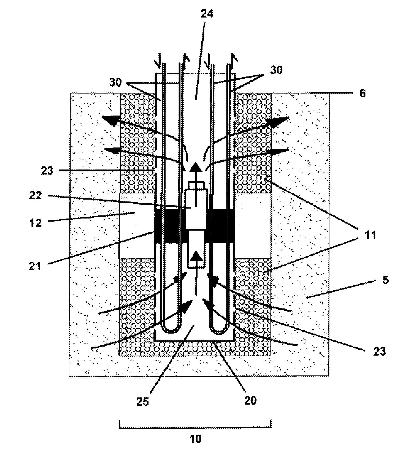
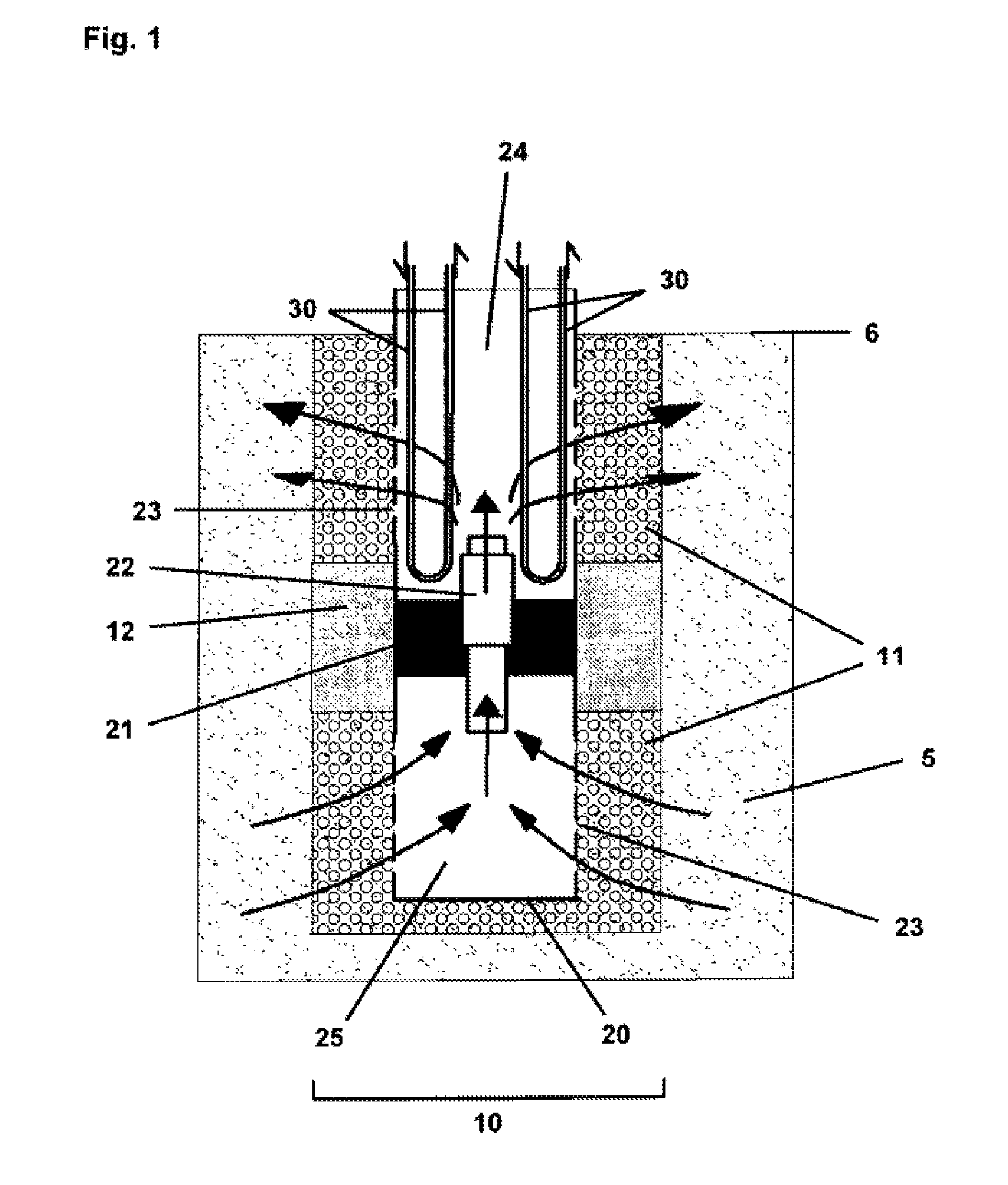
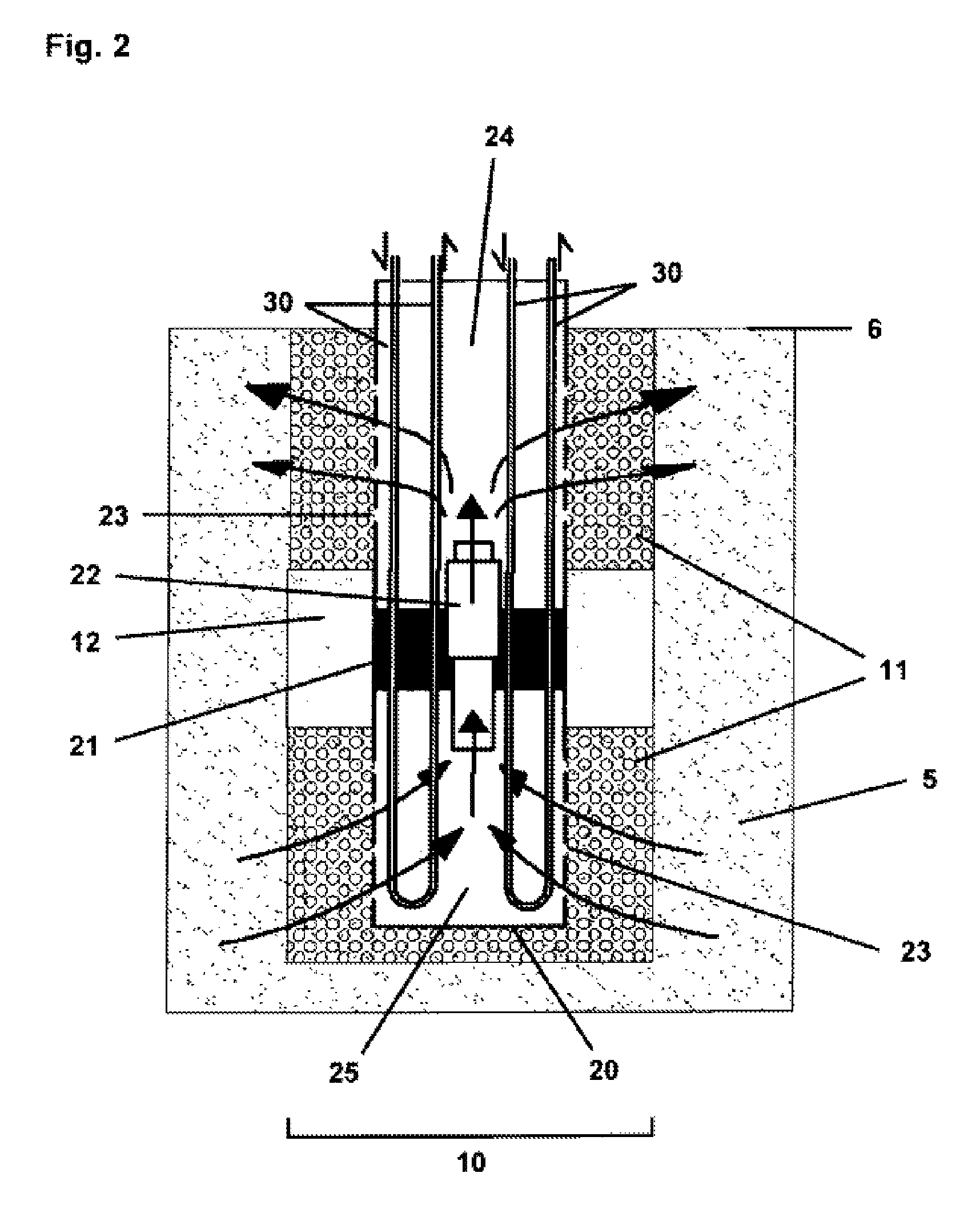
[0083]FIGS. 1, 2 and 3 show a schematic cross-section of an inventive groundwater circulation well with heat exchanger in the upper part of the main pipe (20). A bore (10) is arranged in the soil (5), and the bore (10) ends at the soil surface (6). The main pipe (20) is arranged preferably centrally within the bore (20) and is surrounded by a porous bed (11). Preferably half-way up the loose rock bearing groundwater, the main pipe (20) has a transverse seal (21) which has an opening in the center thereof wherein a pump (22) is arranged. Owing to the transverse seal (21), upper and lower interior spaces (24, 25) are formed in the main pipe (20). In its upper and lower parts the main pipe has through-openings (23) allowing inflow of groundwater into the main pipe or outflow of water conveyed by the pump.

[0084]The pump (22) conveys the water preferably in the direction of the soil surface (6). The arrows in FIG. 1 or 2 indicate the flow direction of the water.

[0085]A sealing material (...


PUM


Abstract

Disclosed is an installation for using geothermal energy, comprising a main pipe (20) in a borehole (10) of a well. The main pipe (20) has several through-holes (23) to the surroundings and is subdivided into a top and a bottom section by means of a transverse closure (21) that has an opening in which a device or a part of a device (22) generating and / or promoting a flow is disposed. At least one heat-utilizing device (30) is arranged within the main pipe (20) which is surrounded at least in the region of the through-holes (23), preferably everywhere, by a porous bed (11) filing at least some of the remaining hollow space of the borehole (10) around the main pipe (20). The porous bed (11) is hydraulically interrupted within the main pipe (20) by a sealing material (12) at the level of the transverse closure (21). Said installation is used for delivering or dissipating heat, decontaminating especially groundwater, and / or generating power.

Description

[0001]This is the U.S. national stage of International application no. PCT / 2008 / 008210, filed Sep. 22, 2008 designating the United States and claiming priority to German application no. DE102007047550.2, filed Sep. 28, 2007, which is incorporated herein by reference.FIELD OF THE INVENTION[0002]The invention relates to a system for utilizing geothermal heat and to the use of said system for the supply or dissipation of heat, for the decontamination of in particular groundwater and / or for the production of electricity.BACKGROUND OF THE INVENTION[0003]The utilization of geothermal heat is regarded as belonging to the regenerative energies. The temperature rises with increasing depth. This increase in temperature is not dependent on seasons or climate, but solely depends on geological and geothermal conditions. For this reason, the utilization of geothermal heat for energy production is a good option in many regions because emission-neutral, especially with respect to CO2 emissions, and...

Claims


Application Information

Patent Timeline
IPC IPC(8): E21B36/00
CPCF24J3/085Y02E10/14F24T10/20Y02E10/10
Inventor VIERNICKEL, MICHAEL
Owner GEO EN ENERGY TECH
Learn More