
Light source apparatus, method of manufacturing the light source apparatus and backlight assembly having the same

a technology of light source apparatus and manufacturing method, which is applied in the manufacture of electric discharge tubes/lamps, lighting and heating apparatus, instruments, etc., can solve the problems of lamp and connection parts being damaged, parts and complex structures, etc., to simplify the manufacturing process steps, reduce the size of modules, and improve the lamination quality of light source apparatus

Inactive Publication Date: 2013-05-07
SAMSUNG DISPLAY CO LTD
View PDF18 Cites 4 Cited by
  • Summary
  • Abstract
  • Description
  • Claims
  • Application Information

AI Technical Summary

Benefits of technology

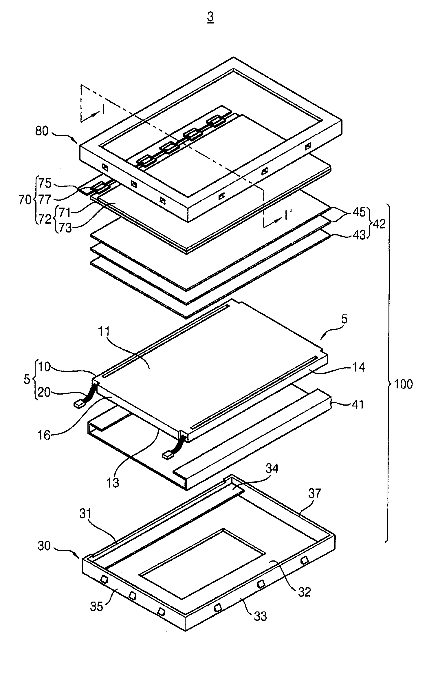
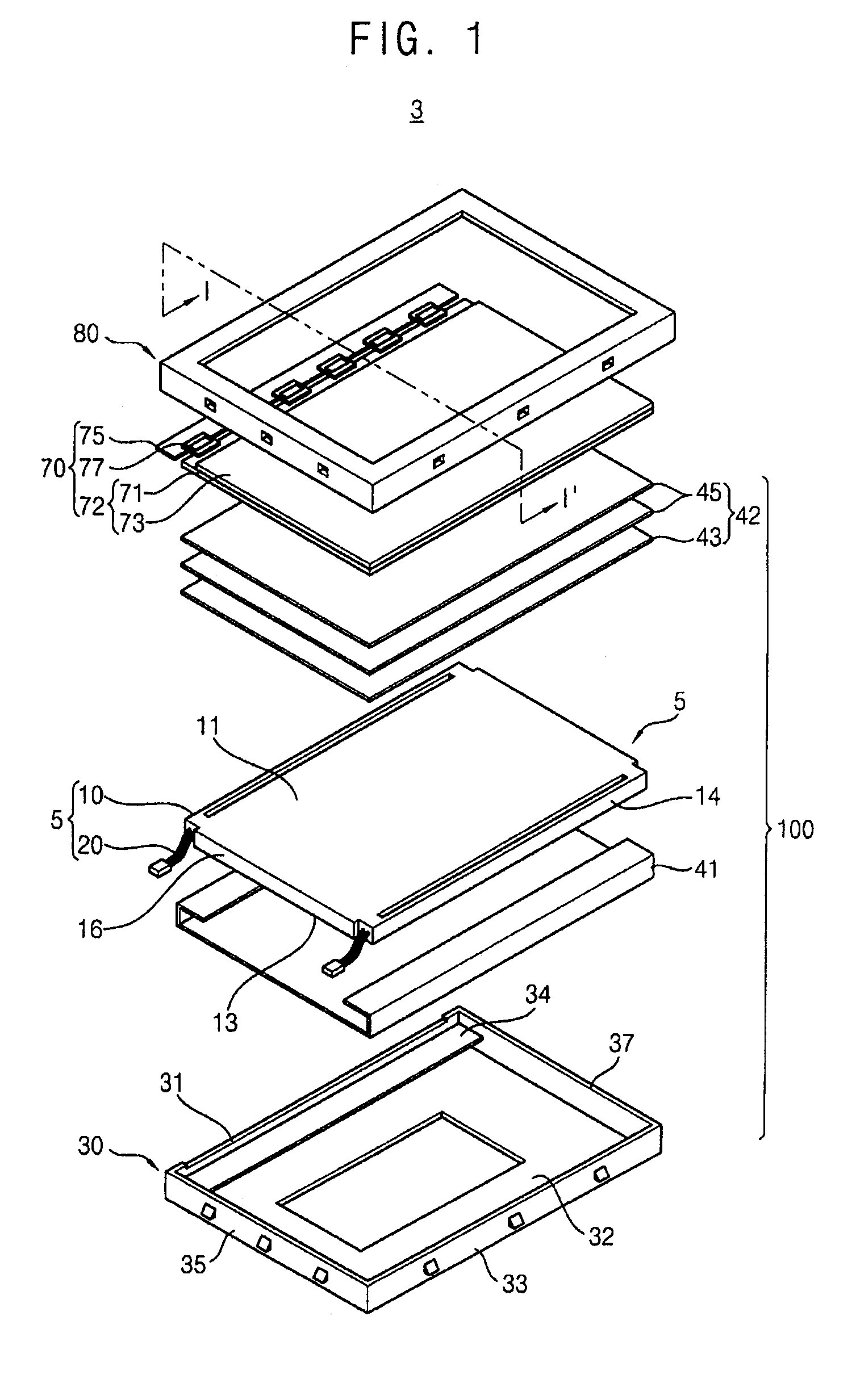
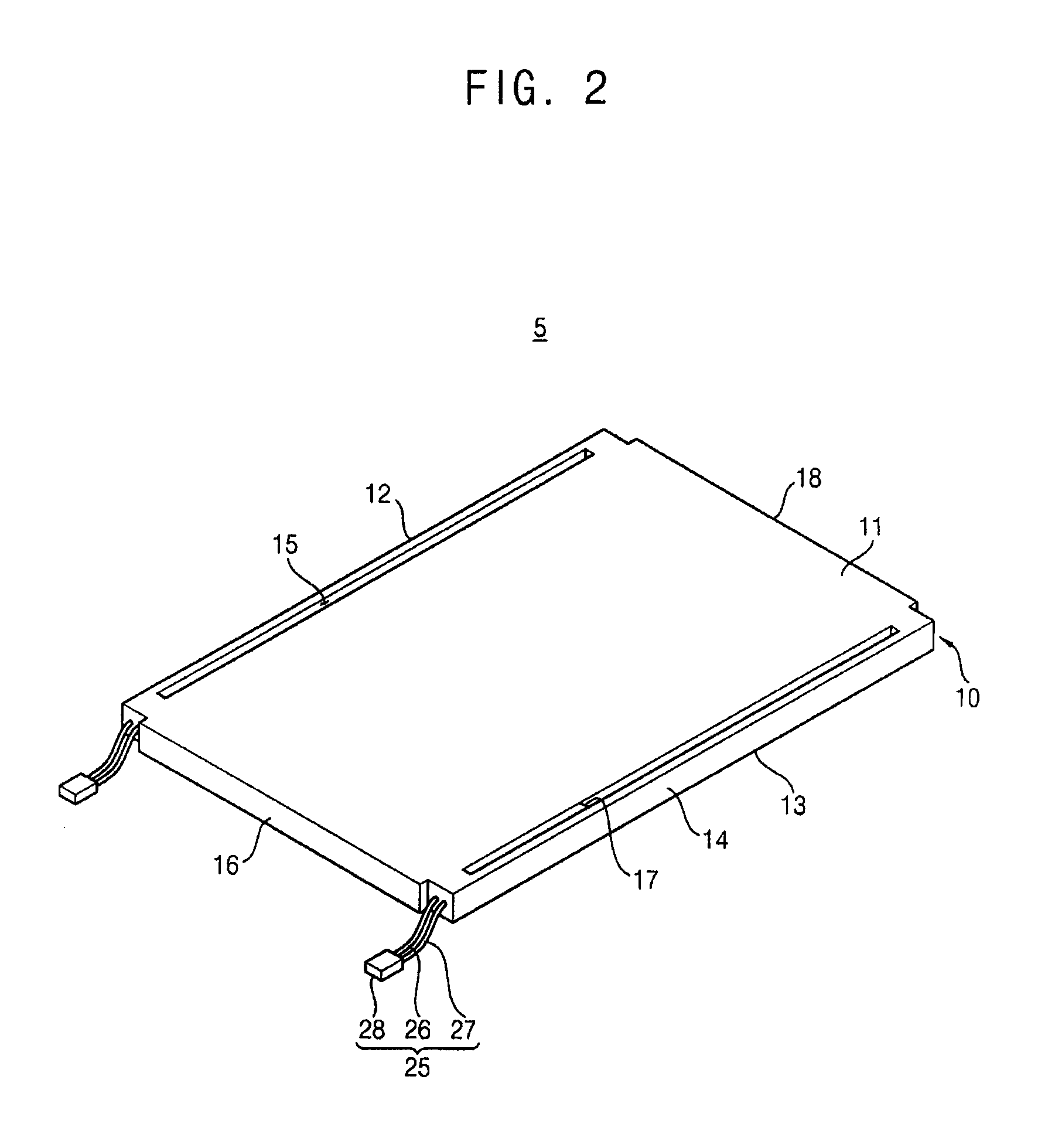
The present invention is a light source apparatus that is more efficient and easy to assemble, and a method of manufacturing it. It also simplifies the steps of manufacturing processes for a backlight assembly, improving the lamination quality and preventing external damage. This invention is useful for a backlight assembly in a flat panel display apparatus that includes an LGP.

Problems solved by technology

The backlight assembly may include many parts and have a complex structure.
Also, the lamp and connection portion may be damaged during manufacturing.

Method used


Image

  • Light source apparatus, method of manufacturing the light source apparatus and backlight assembly having the same
  • Light source apparatus, method of manufacturing the light source apparatus and backlight assembly having the same
  • Light source apparatus, method of manufacturing the light source apparatus and backlight assembly having the same

Examples


Embodiment Construction

[0035]The present invention is described more fully hereinafter with reference to the accompanying drawings, in which example embodiments of the present invention are shown. The present invention may, however, be embodied in many different forms and should not be construed as limited to the example embodiments set forth herein. Rather, these example embodiments are provided so that this disclosure will be thorough and complete, and will fully convey the scope of the present invention to those skilled in the art. In the drawings, relative sizes of features, layers and regions may be exaggerated for / / clarity.

[0036]It will be understood that when an element or layer is described as being “on,”“connected to” or “coupled to” another element or layer, it can be either directly on, connected or coupled to the other element or layer, or via intervening elements or layers. In contrast, when an element is described as being “directly on,”“directly connected to” or “directly coupled to” anoth...


PUM


Abstract

In a light source apparatus, a method of manufacturing the light source and a backlight assembly having the same, a light guide plate (LGP) includes an upper surface and a lower surface facing each other and a first side surface and a second side surface. The light source is placed in the LGP adjacent to the first side surface and emits light toward the second side surface. The power supply unit is electrically connected to the light source and partially placed in the LGP. The light source may include a lamp or a light-emitting diode (LED). The power supply unit may include a wire or a power supply substrate. The light source apparatus may be formed by an injection molding process using lower and upper mold frames. Therefore, backlight assembly size, the number of parts and manufacturing steps may be decreased, and the illumination quality may be improved.

Description

PRIORITY STATEMENT[0001]This application claims priority under 35 U.S.C. §119 to Korean Patent Application No. 2008-61522, filed in the Korean Intellectual Property Office (KIPO) on Jun. 27, 2008, the contents of which are herein incorporated by reference in their entirety.BACKGROUND OF THE INVENTION[0002]1. Field of the Invention[0003]The present invention relates to a light source apparatus, a method of manufacturing the light source apparatus, and a backlight assembly having the light source apparatus. In particular, the light source apparatus is used in a display apparatus as a backlight source.[0004]2. Description of the Related Art[0005]Generally, a liquid crystal display (LCD) device includes a display panel assembly and a backlight assembly which provides backside illumination. The display panel assembly displays images with the light. The backlight assembly is classified as either an edge illumination type or a direct illumination type.[0006]In the edge illumination type ba...

Claims


Application Information

Patent Timeline
Patent Type & Authority Patents(United States)
IPC IPC(8): F21V7/04
CPCG02B6/0083G02B6/0091G02B6/0001G02F1/1335
Inventor RYU, HO-HANKIM, TAE-SEOKKIM, JIN-GWAN
Owner SAMSUNG DISPLAY CO LTD
Learn More