Method of manufacturing a substrate for liquid ejection head

a technology of liquid ejection head and substrate, which is applied in the direction of printing, electrical equipment, basic electric elements, etc., can solve the problems of reducing the opening accuracy of the ink supply port and becoming difficult to form the opening correspondingly to the etching mask, so as to improve the accuracy of the opening dimension of the liquid supply port.

Inactive Publication Date: 2013-05-07
CANON KK
View PDF13 Cites 1 Cited by
  • Summary
  • Abstract
  • Description
  • Claims
  • Application Information

AI Technical Summary

Benefits of technology

[0007]Therefore, the present invention has an object to provide a method of manufacturing a substrate for liquid ejection head, which is capable of suppressing an influence to be caused by defects such as flaws in the substrate, and improving an accuracy of an opening dimension of a liquid supply port.

Problems solved by technology

However, in some cases, an opening accuracy of the ink supply port reduces because of flaws and defects in a silicon substrate, flaws in an etching mask, and the like.
In this case, it is possible to improve the accuracy, but it becomes difficult to form the opening correspondingly to the etching mask.

Method used


Image

  • Method of manufacturing a substrate for liquid ejection head
  • Method of manufacturing a substrate for liquid ejection head
  • Method of manufacturing a substrate for liquid ejection head

Examples


example

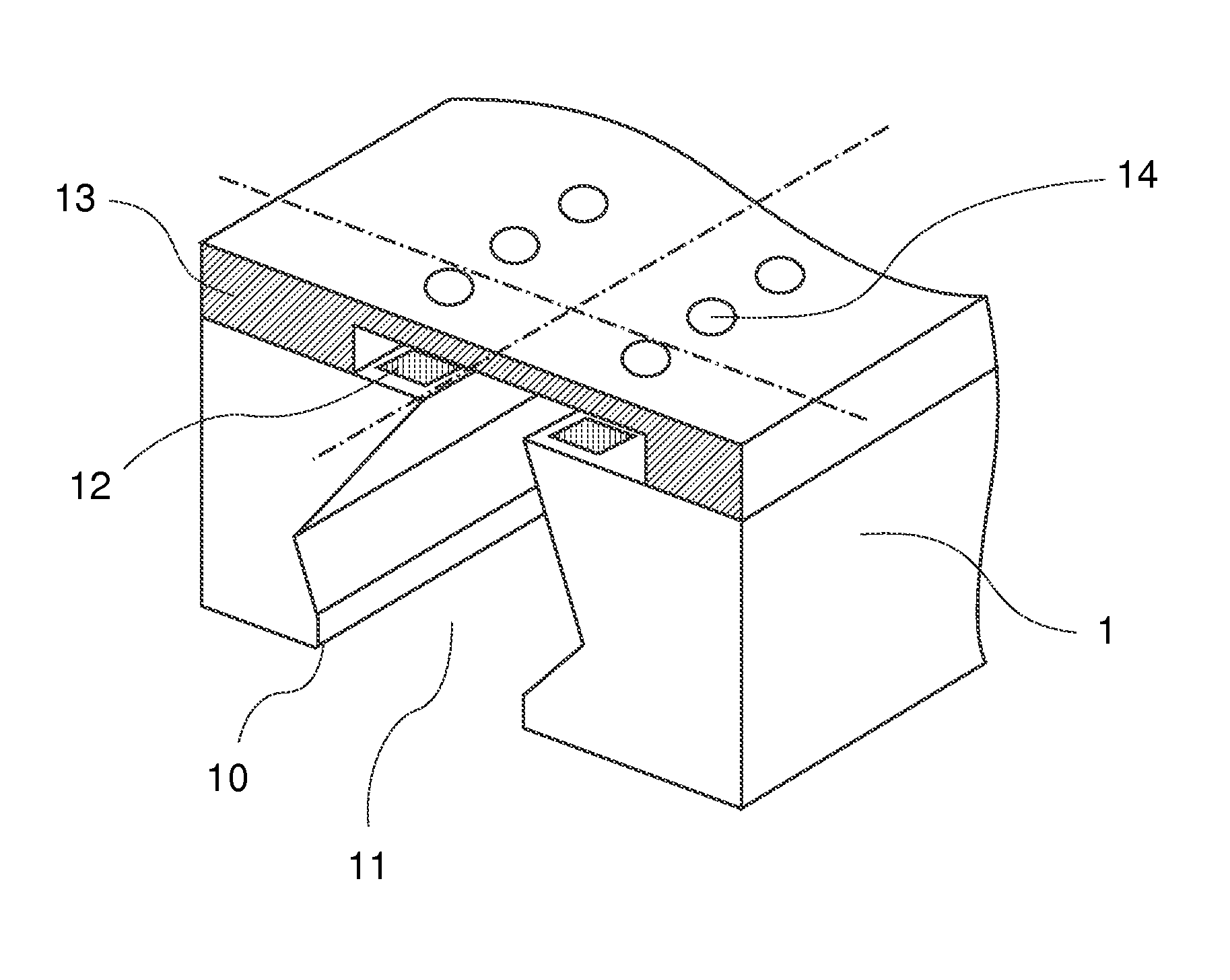
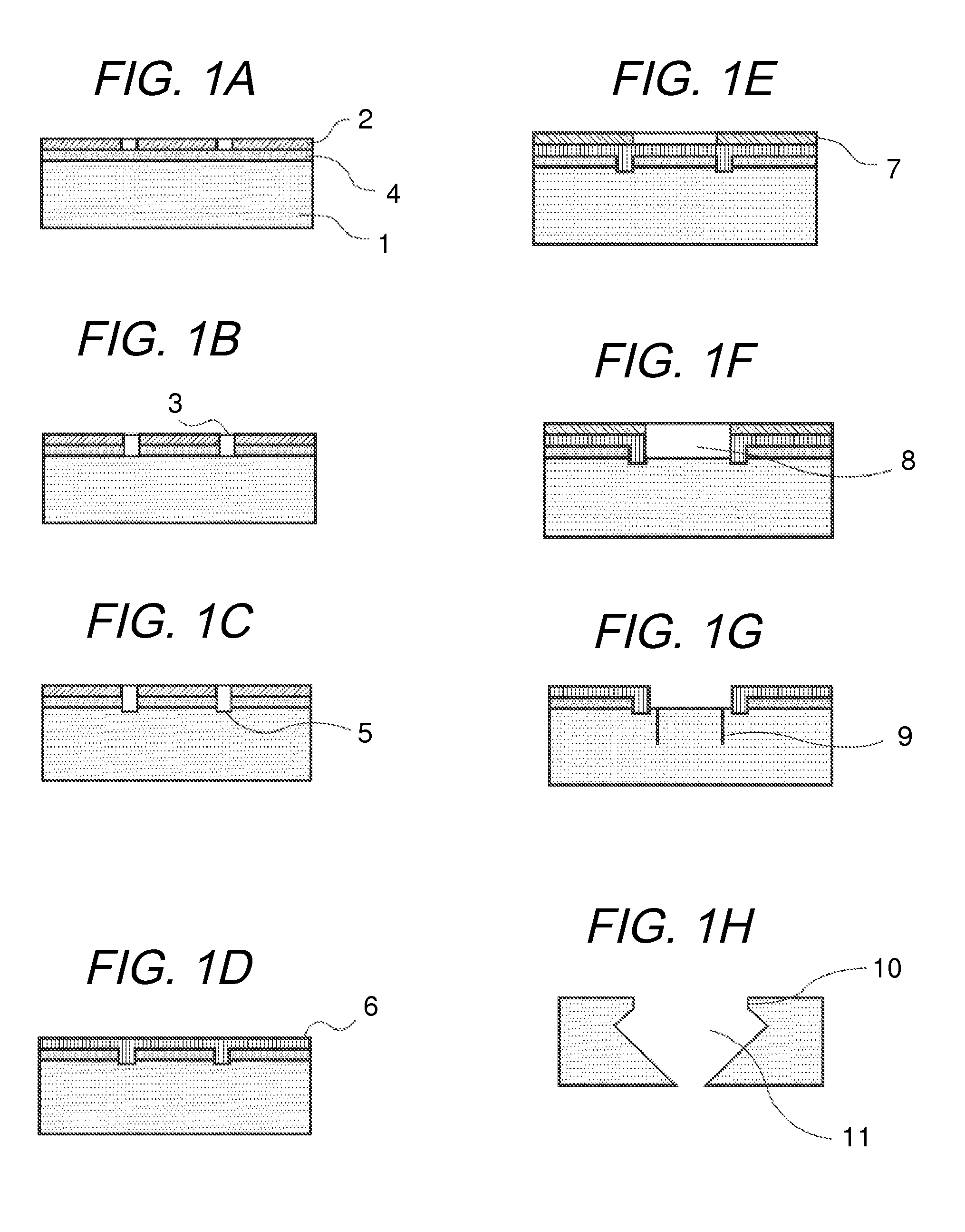
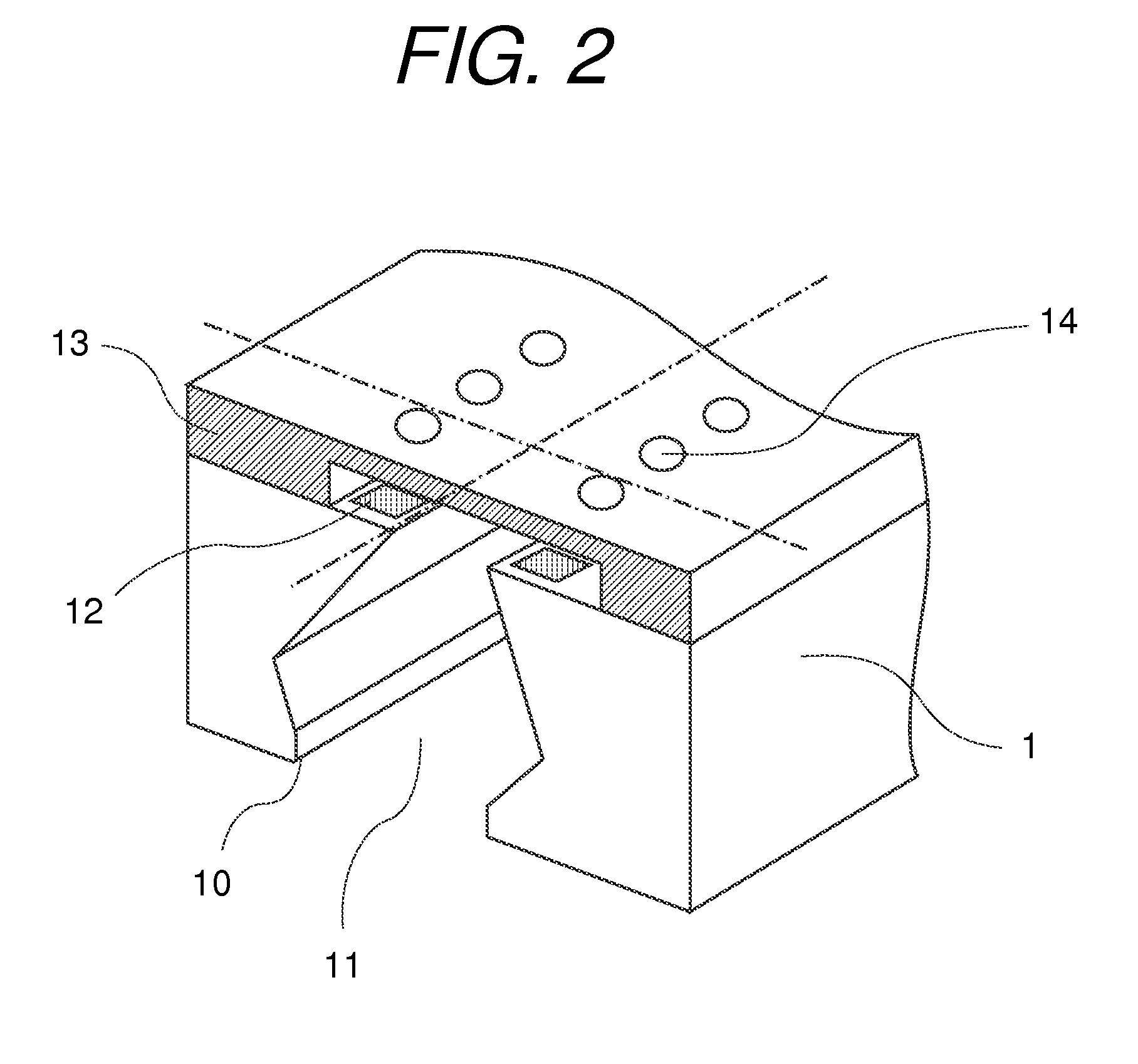
[0053]Referring to FIGS. 1A to 1H, a method of manufacturing a substrate for ink jet recording head according to an example is described. Note that, a finished head state of the example is illustrated in FIG. 2.

[0054]As illustrated in FIG. 1A, the first protective layer 4 was formed on the rear surface (upper surface in FIG. 1A) of the silicon substrate 1. On the first protective layer 4, the first resist mask 2 having a pattern corresponding to the groove portion was formed.

[0055]The first protective layer 4 was formed by thermal oxidation of the silicon substrate.

[0056]The first resist mask 2 was formed by, after coating a positive resist by spin coating on the rear surface of the silicon substrate 1, performing exposure and developing processing. As the positive resist, IP5700 (trade name, manufactured by TOKYO OHKA KOGYO CO., LTD.) was used.

[0057]Next, as illustrated in FIG. 1B, the first protective layer 4 was subjected to etching, and the first opening 3 for forming the groove...


PUM


Abstract

Provided is a method of manufacturing a substrate for liquid ejection head, including: forming a groove portion by etching on one surface side of a silicon substrate, the groove portion being formed so as to surround a portion at which a liquid supply port is to be formed on an inner side of the groove portion; forming a protective layer on the one surface side of the silicon substrate, the protective layer being formed inside the groove portion and on an outer side of the groove portion; and forming the liquid supply port by subjecting the silicon substrate to crystal anisotropic etching treatment with use of the protective layer as a mask.

Description

BACKGROUND OF THE INVENTION[0001]1. Field of the Invention[0002]The present invention relates to a method of manufacturing a substrate for liquid ejection head to be used for a liquid ejection head which ejects liquid such as ink liquid.[0003]2. Description of the Related Art[0004]In recent years, in an ink jet recording head, increase in the number of ink supply ports and narrowing of pitches between the ink supply ports have been progressing. In this trend, it is required to surely secure an adhering area between a rear surface of a substrate of an ink jet recording head provided with supply ports and a support member for supporting the ink jet recording head, to thereby maintain an adhering strength. Therefore, in order to maintain the adhering area, it is desired to reduce fluctuations in shape of the ink supply ports. However, in some cases, an opening accuracy of the ink supply port reduces because of flaws and defects in a silicon substrate, flaws in an etching mask, and the ...

Claims


Application Information

Patent Timeline
Patent Type & Authority Patents(United States)
IPC IPC(8): H01L21/00
CPCB41J2/14145B41J2/1603B41J2/1628B41J2/1629B41J2/1631B41J2/1634B41J2/1642B41J2/1645B41J2/1646
Inventor YONEMOTO, TAICHIABO, HIROYUKIKISHIMOTO, KEISUKE
Owner CANON KK
Why Eureka
Try Eureka