
Multiple die paddle leadframe and semiconductor device package

Active Publication Date: 2013-05-07
NVIDIA CORP
View PDF7 Cites 21 Cited by
  • Summary
  • Abstract
  • Description
  • Claims
  • Application Information

AI Technical Summary

Benefits of technology

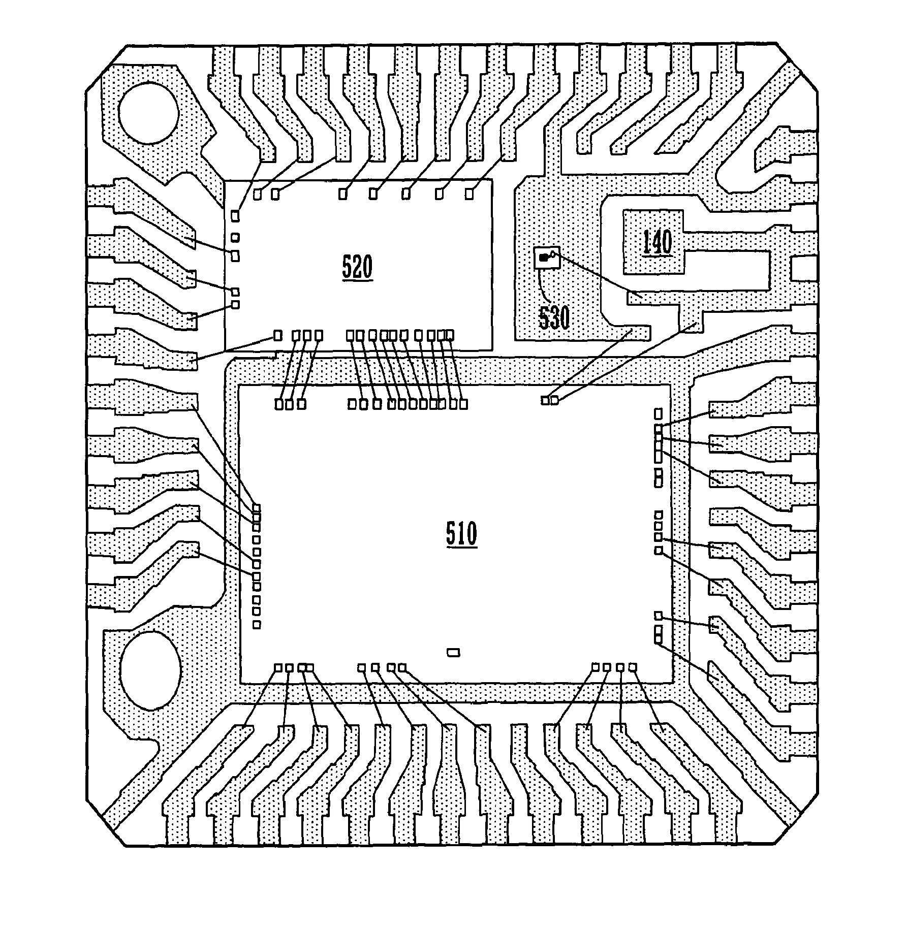
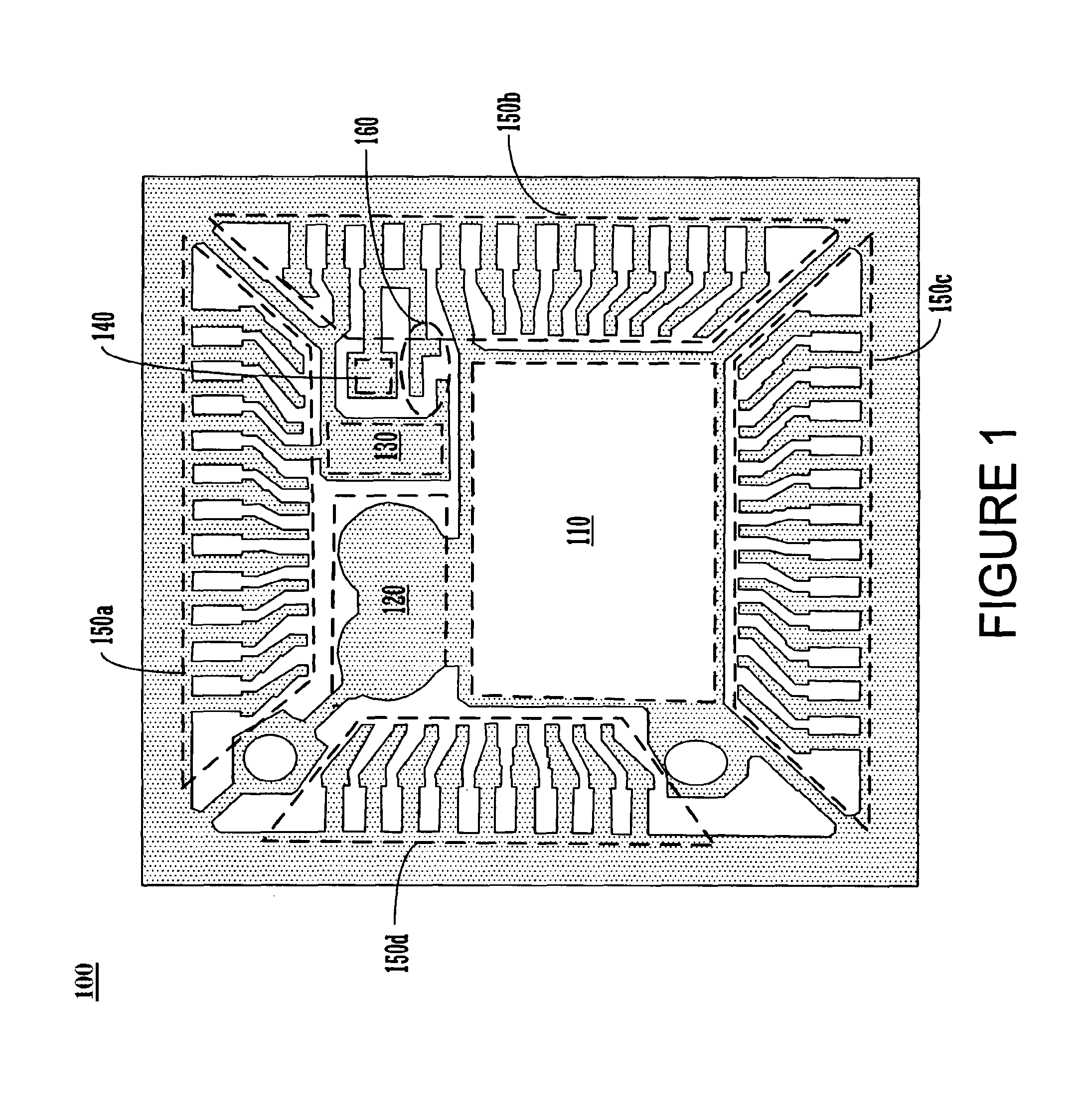
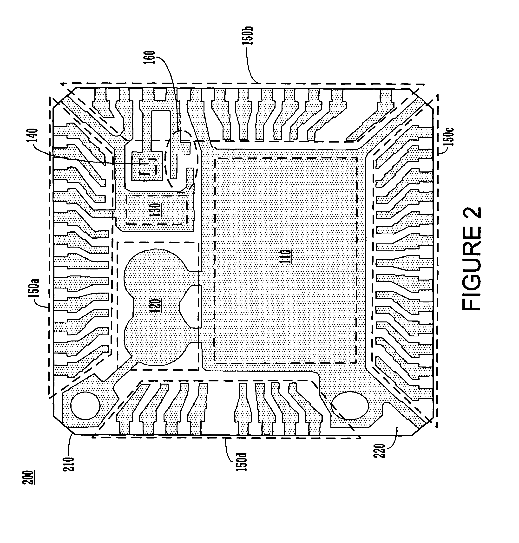
The patent text discusses a leadframe and semiconductor device package with multiple semiconductor device die paddles that can accommodate multiple semiconductor devices. The leadframe includes a full-metal die paddle and a reduced-metal die paddle that helps reduce the amount of die attach material used to bond semiconductor devices to the leadframe. The leadframe also allows for electrical coupling of multiple semiconductor devices and provides heat dissipation. The technical effects of this invention include smaller and more cost-effective multi-die systems with increased component density.

Problems solved by technology

Additionally, the complexity of each component used in the products increases to carry out the enhanced functionality of the product.
As such, size and cost requirements for the products tend to limit product functionality.
Further, the increased number, density and complexity of components increases the overall heat generated by the products, thereby presenting additional issues for the design of these products.
As such, conventional multi-die systems have a relatively large package footprint, thereby limiting integrated circuit density and making them unsuitable for use in higher-performance applications.
Additionally, product functionality is further limited by the use of PCB or laminate substrates which provide a relatively high product and assembly cost and poor heat dissipation for heat-generating components.

Method used


Image

  • Multiple die paddle leadframe and semiconductor device package
  • Multiple die paddle leadframe and semiconductor device package
  • Multiple die paddle leadframe and semiconductor device package

Examples


Embodiment Construction

[0019]Reference will now be made in detail to embodiments of the present invention, examples of which are illustrated in the accompanying drawings. While the present invention will be discussed in conjunction with the following embodiments, it will be understood that they are not intended to limit the present invention to these embodiments alone. On the contrary, the present invention is intended to cover alternatives, modifications, and equivalents which may be included with the spirit and scope of the present invention as defined by the appended claims. Furthermore, in the following detailed description of the present invention, numerous specific details are set forth in order to provide a thorough understanding of the present invention. However, embodiments of the present invention may be practiced without these specific details. In other instances, well-known methods, procedures, components, and circuits have not been described in detail so as not to unnecessarily obscure aspect...


PUM


Abstract

A leadframe and semiconductor device package with multiple semiconductor device die paddles for accepting multiple semiconductor devices is disclosed, wherein the leadframe increases semiconductor device density and reduces cost by integrating the multiple dies into a semiconductor device package with a relatively small footprint. The leadframe may include at least one full-metal die paddle and at least one reduced-metal die paddle, which may form a unified or hybrid die paddle. The leadframe may enable electrical coupling of multiple semiconductor devices to a common leadfinger and / or die paddle, where internal leadfingers coupled to the common leadfingers and / or die paddles may receive the electrical coupling means from the semiconductor device. Surfaces of one or more die paddles of the leadframe may be exposed to the outside of the semiconductor device package to enable electrical testing of and / or provide heat dissipation from one or more of the semiconductor devices attached to the leadframe.

Description

RELATED APPLICATIONS[0001]The present application is related to and claims the benefit of U.S. Provisional Patent Application Ser. No. 60 / 927,735, filed May 4, 2007, entitled “MULTI-DIE PADDLE LEADFRAME FOR INTEGRATED OPTICAL SENSOR SYSTEM,” naming Bo Chang and Carlo Gamboa as inventors, assigned to the assignee of the present invention. That application is incorporated herein by reference in its entirety and for all purposes.BACKGROUND OF THE INVENTION[0002]As the capabilities and features of consumer products increase, the number and density of the components used in the products also increases. Additionally, the complexity of each component used in the products increases to carry out the enhanced functionality of the product. As such, size and cost requirements for the products tend to limit product functionality. Further, the increased number, density and complexity of components increases the overall heat generated by the products, thereby presenting additional issues for the d...

Claims


Application Information

Patent Timeline
IPC IPC(8): H01L23/48
CPCH01L23/49503H01L23/49575H01L2224/32245H01L2224/48137H01L2224/48247H01L2224/73265H01L2924/00012H01L24/32H01L24/48H01L24/49H01L2224/49177H01L2924/12035H01L24/73H01L2224/05554H01L2924/00014H01L2924/00H01L2224/45099H01L2224/45015H01L2924/207
Inventor GAMBOA, CARLOCHANG, BO
Owner NVIDIA CORP
Learn More