Counting pixel with good dynamic range properties
a dynamic range and counting pixel technology, applied in the field of counting pixel with good dynamic range properties, can solve the problems of large area and power consumption, complex counting pixel devices, and yield killing digital counters
- Summary
- Abstract
- Description
- Claims
- Application Information
AI Technical Summary
Benefits of technology
Problems solved by technology
Method used
Image
Examples
first embodiment
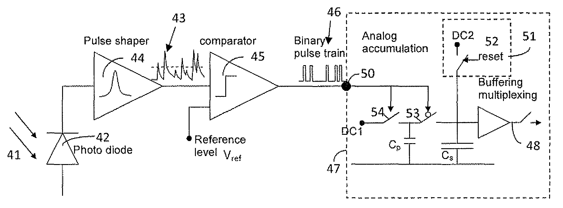
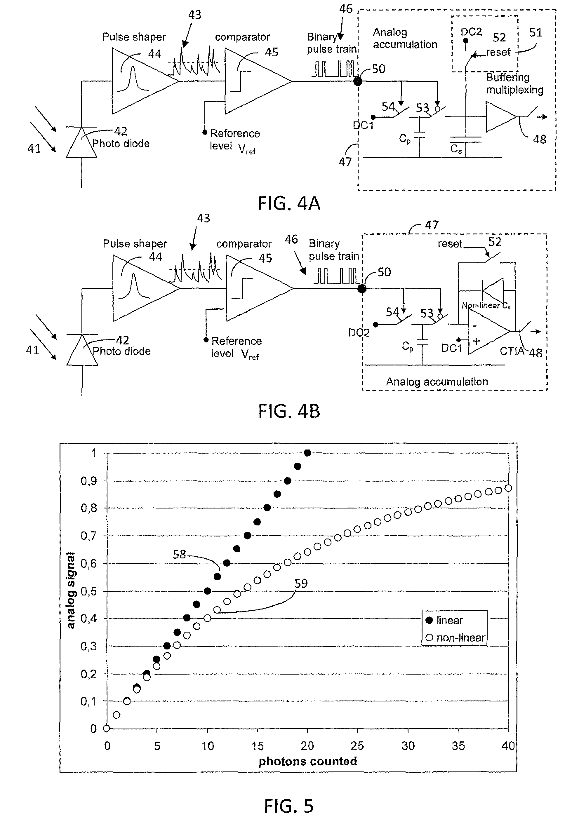
[0111]In a first embodiment, the sharpening operation, i.e. suppressing signals in some of the pixels of a neighborhood, may be performed on the photoreceptor signal itself (=on photo charge or photocurrent) as illustrated in FIG. 10. This drawing illustrates two pixels 100, 101 of an array of pixels. Embodiments of the present invention are, however, not limited to a neighborhood of only two pixels; two pixels only are illustrated for reasons of clarity. Each pixel 100, 101 comprises a radiation receptor 42, e.g. phototransducer 42 (such as for example photodiode, PIN diodes, photoresistors, wire chambers, dynodes, photomultipliers, micro channel plates, avalanche photodiodes, monolithic or hybrid, for converting the electromagnetic radiation (such as for example X-rays or visible light) or impinging high energy particles 41 (such as for example alpha and beta radiation, electron beam, and subnuclear particles) into a first radiation signal 102. The impinging radiation may be singl...
second embodiment
[0114]In a second embodiment, the sharpening operation, i.e. suppressing signals in some of the pixels of a neighborhood, may be performed in the analog pulse domain, i.e. on the resulting signal from the pulse shaper 44. Components illustrated in FIG. 11 which are as in FIG. 10 are not discussed here again. The analog domain pulses 43 on which the sharpening operation is performed in this case have analog wave forms, with maybe different amplitude, start / end time, duration, rise time, fall time, integral, sharpness or maximum.
[0115]In the embodiment illustrated in FIG. 11, a “winner-take-all” circuit 110 (WTA) is implemented, as also disclosed by J. Lazzaro et al. in “Winner-take-all networks of O(n) Complexity”, Advances in neural information processing systems, D. S. Touretzky Ed., Vol. 2, pp. 703-711, Morgan Kaufmann, San Mateo, Calif., 1989, or by Minglian Liu in “CMOS winner-take-all circuits: a tutorial”, EDN Jun. 26, 2007, http: / / www.edn.com / article / CA6454765.html#ref. Both ...
third embodiment
[0118]In a third embodiment, the sharpening operation, i.e. suppressing signals in some of the pixels of a neighborhood, may be performed on the result of the comparator 45, as illustrated in FIG. 12, i.e. on the digital pulse train 46. Components illustrated in FIG. 12 which are as in FIG. 10 are not discussed here again. The digital domain pulses forming the pulse train 46 have all the same amplitude but may differ in start / end time and / or duration.
[0119]The embodiment illustrated in FIG. 12 comprises a variant of WTA: a “First-Takes-all” (FTA) circuit 120: the pulse that comes first suppresses its neighbors. This implementation assumes that the strongest analog pulse propagates first. In fact, the combination of the comparator pulse and the FTA acts effectively as a WTA, and can be considered as a particular implementation of a WTA.
[0120]A practical implementation of “First takes all” is that the digital pulse that comes first in a neighborhood wins.
PUM
 Abstract
Description
Claims
Application Information
 - R&D
- Intellectual Property
- Life Sciences
- Materials
- Tech Scout
- Unparalleled Data Quality
- Higher Quality Content
- 60% Fewer Hallucinations
Browse by: Latest US Patents, China's latest patents, Technical Efficacy Thesaurus, Application Domain, Technology Topic, Popular Technical Reports.
© 2025 PatSnap. All rights reserved.Legal|Privacy policy|Modern Slavery Act Transparency Statement|Sitemap|About US| Contact US: help@patsnap.com


