Shape memory alloy actuation apparatus

Active Publication Date: 2013-05-14
CAMBRIDGE MECHATRONICS
View PDF36 Cites 97 Cited by
  • Summary
  • Abstract
  • Description
  • Claims
  • Application Information

AI Technical Summary

Benefits of technology

[0044]All the aspects of the present invention may be applied to a movable element which is a camera lens element, the movement axis being the optical axis of the ca

Problems solved by technology

This is particularly true for a camera lens element for which these deviances may cause a degradation of image quality.
An issue in an SMA apparatus in which the actuator is an SMA actuator and the suspension system comprises a plurality of flexures, is to design an apparatus to provide a desired range of movement.
Firstly this raises the temperature at which the stress in the SMA material is sufficient to cause contraction against the biasing means.
Secondly, in the rest state, the pre-stressing of the biasing means holds the movable element firmly against the end-stop.
However, this directly reduces the range of movement.
However, on deflection of the flexures it also causes the material limits of the flexures to be approached more quickly and so can indirectly reduce the range of movement.
An example of a type of movable element where tilt is an issue is where the movable element is a

Method used


Image

  • Shape memory alloy actuation apparatus
  • Shape memory alloy actuation apparatus
  • Shape memory alloy actuation apparatus

Examples


Embodiment Construction

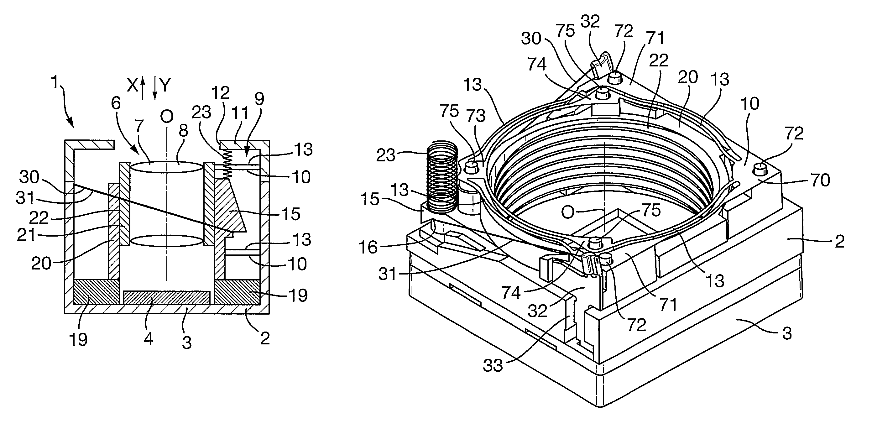
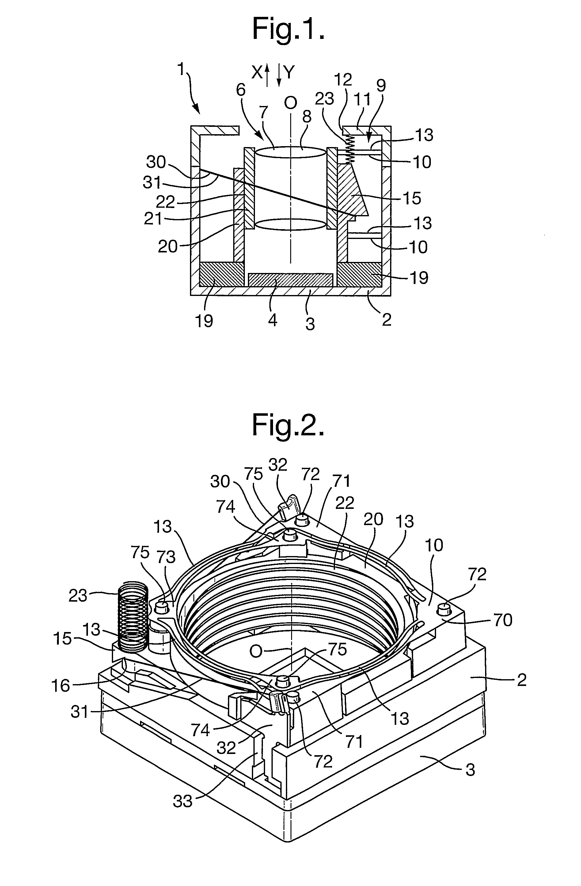
[0054]There will first be described the structure of a camera 1 incorporating an SMA actuation apparatus. The camera 1 is to be incorporated in a portable electronic device such as a mobile telephone, media player or portable digital assistant.

[0055]The camera 1 is shown schematically in FIG. 1 which is a schematic side view of the various functional components of the SMA actuation apparatus of the camera 1. The camera 1 comprises a support structure 2 which may be made of plastic. The support structure has a base portion 3 on which there is mounted an image sensor 4 having an array of light sensitive pixels. The image sensor 4 is typically packaged into a substrate, optionally with a protective cover glass or infrared (IR) filter. The image sensor may be a CCD (charge-coupled device) or a CMOS (complimentary metal-oxide-semiconductor) device. As viewed along the optical axis O, the base portion 3 is generally square and all the components of the camera 1 are within the footprint th...


PUM


Abstract

An SMA actuation apparatus comprises a camera lens element supported on a support structure by a plurality of flexures. An SMA wire at an acute angle to the movement axis and a biasing element are connected between the support structure and the movable element. A component of the force applied by the SMA wire perpendicular to the movement axis compresses the flexures causing them to apply a force to the movable element having a component along the movement axis in the same direction as the SMA wire. An end-stop limits the movement of the movable element, and the moment applied by the end-stop to the movable element about the center of stiffness is equal to the moment applied by the SMA wire about the center of stiffness at the point when the movable element loses contact with the end-stop on contraction of the SMA wire.

Description

CROSS-REFERENCE TO RELATED APPLICATIONS[0001]This application is a 371 U.S. National Stage of International Application No. PCT / GB2010 / 000125, filed Jan. 27, 2010. This application claims priority to British patent application No. 0901952.2, filed with the Intellectual Property Office on Feb. 9, 2009, British patent application No. 0903226.9, filed with the Intellectual Property Office on Feb. 26, 2009, and British patent application No. 0913299.4, filed with the Intellectual Property Office on Jul. 30, 2009, all of which applications are herein incorporated by reference in their entirety.[0002]The present invention relates to an apparatus in which an actuator is used to drive movement of a movable element supported on a support structure. In some aspects, it relates in particular to an apparatus which is a shape memory alloy (SMA) actuation apparatus using SMA material as the actuator.[0003]The present invention is generally applicable to any type of movable element but has particu...

Claims


Application Information

Patent Timeline
IPC IPC(8): G02B7/02G03B3/10H04N5/225
CPCF03G7/065G02B7/08G03B3/10
Inventor BROWN, ANDREW BENJAMIN DAVIDTOPLISS, RICHARD
Owner CAMBRIDGE MECHATRONICS
Why Eureka
Try Eureka