
Marking apparatus having enhanced features for underground facility marking operations, and associated methods and systems

Active Publication Date: 2013-05-14
CERTUSVIEW TECH
View PDF529 Cites 12 Cited by
  • Summary
  • Abstract
  • Description
  • Claims
  • Application Information

AI Technical Summary

Benefits of technology

The patent text discusses a way to reduce uncertainties in locating underground facilities during construction. By collecting information about the marking operation, excavators can have a better understanding of the risks and take appropriate measures to prevent damage or injury. The patent also describes marking devices that can collect information about the location, time, and color of the marking material dispensed during a marking operation. This information is then stored in an electronic record, which can be accessed and analyzed to provide further information about the performance of the marking operation. Overall, this approach helps improve the accuracy and safety of the marking operation.

Problems solved by technology

In many instances, excavators arriving to a work site have only physical locate marks on which to rely to indicate a presence or absence of underground facilities, and they are not generally privy to information that may have been collected previously during the locate operation.
More specifically, Applicants have recognized and appreciated that conventional techniques for using a locate device to detect underground facilities are sometimes tentative and typically iterative in nature, and use of locate devices with GPS capabilities may result in redundant, spurious and / or incomplete geographic location data collected by such devices.
In view of the foregoing, it may be readily appreciated that collecting and logging geographic location information throughout this process may result in excessive and / or imprecise data, or in some instances incomplete relevant data (e.g., in the case of signal loss / broken tracer wire), from which it may be difficult to cull the data that is truly complete and representative of where the underground facility ultimately was detected.
Furthermore, Applicants have recognized and appreciated that the location at which an underground facility ultimately is detected during a locate operation is not always where the technician physically marks the ground, pavement or other surface during a marking operation; in fact, technician imprecision or negligence, as well as various ground conditions and / or different operating conditions amongst different locate device, may in some instances result in significant discrepancies between detected location and physical locate marks.

Method used


Image

  • Marking apparatus having enhanced features for underground facility marking operations, and associated methods and systems
  • Marking apparatus having enhanced features for underground facility marking operations, and associated methods and systems
  • Marking apparatus having enhanced features for underground facility marking operations, and associated methods and systems

Examples


Embodiment Construction

[0123]Following below are more detailed descriptions of various concepts related to, and embodiments of, inventive marking apparatus having enhanced features for underground facility marking operations, and associated methods and systems. It should be appreciated that various concepts introduced above and discussed in greater detail below may be implemented in any of numerous ways, as the disclosed concepts are not limited to any particular manner of implementation. Examples of specific implementations and applications are provided primarily for illustrative purposes.

[0124]I. Overview

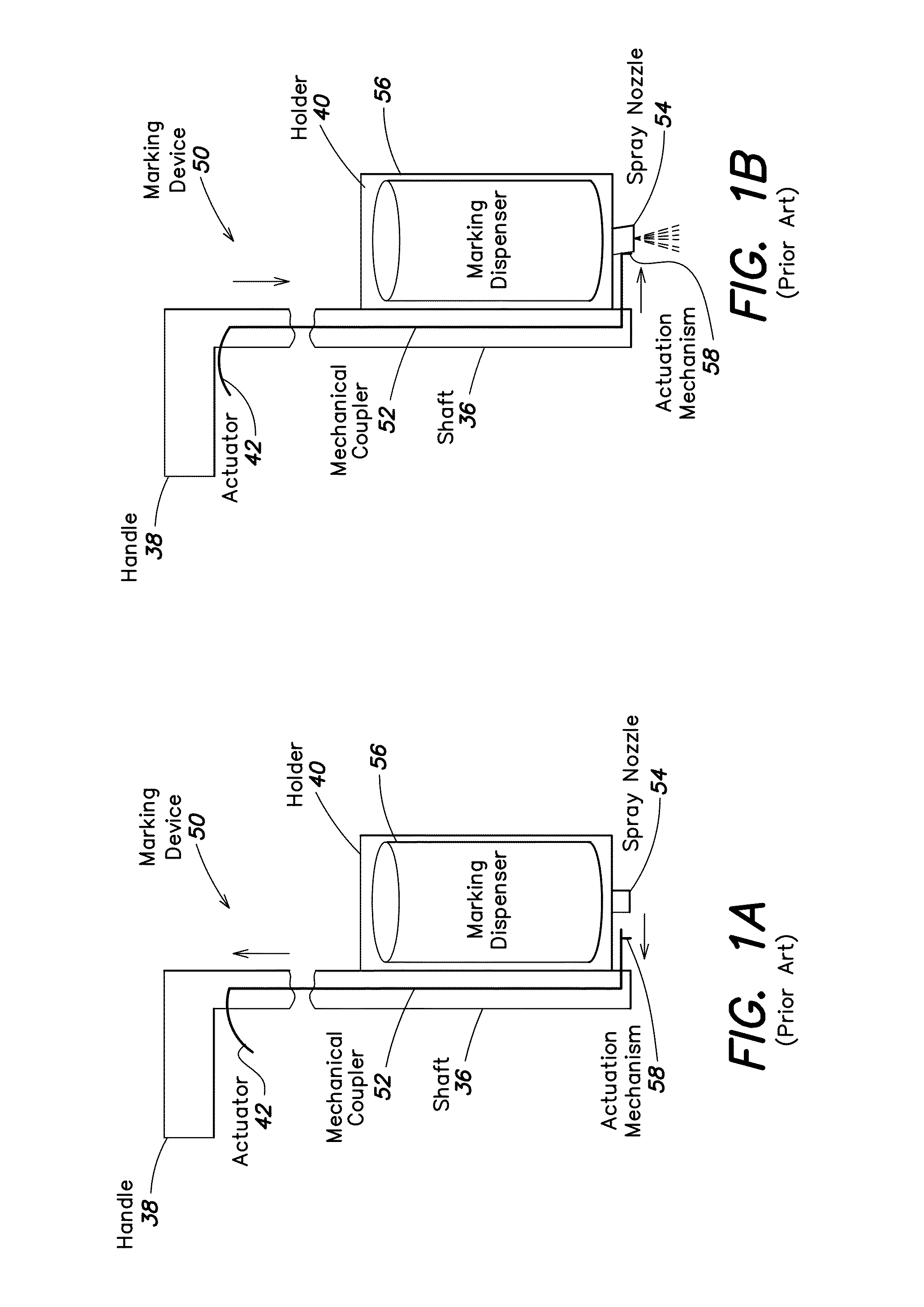
[0125]In some embodiments of the present invention, a marking device employed by a locate technician to dispense marking material is particularly configured to acquire “marking information” relating to a marking operation based at least in part on actuations of the marking device, and create an electronic record of at least some of the marking information. As discussed in greater detail below, examples ...


PUM


Abstract

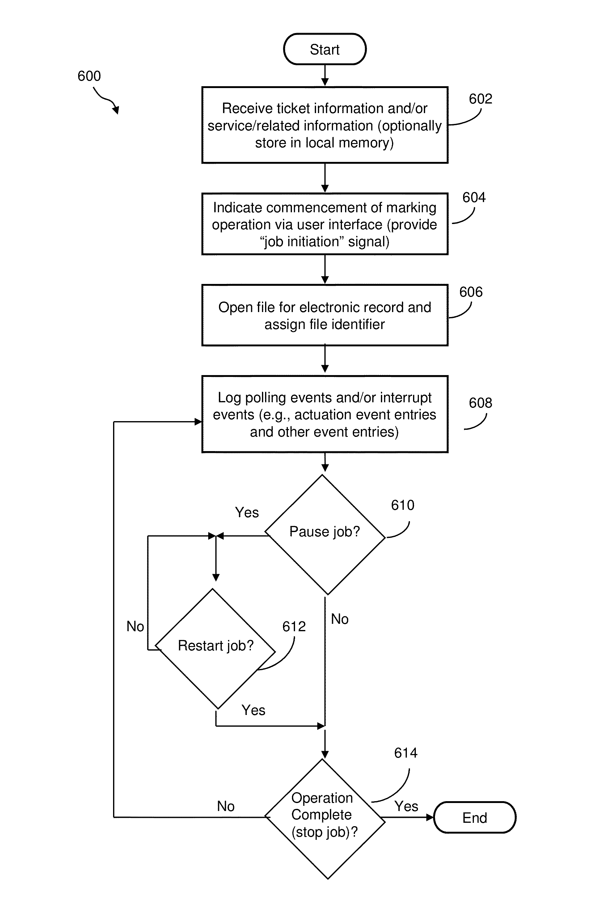
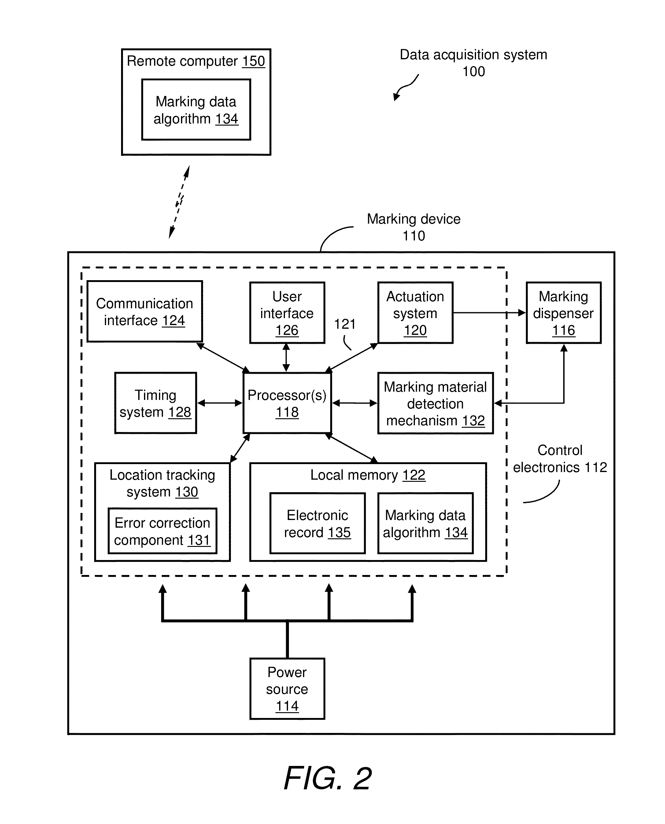
Marking information relating to use of a marking device to perform a marking operation may be acquired from one or more input devices, logged / stored in local memory of a marking device, formatted in various manners, processed and / or analyzed at the marking device itself, and / or transmitted to another device (e.g., a remote computer / server) for storage, processing and / or analysis. In one example, a marking device may include one or more environmental sensors and / or operational sensors, and the marking information may include environmental information and operational information derived from such sensors. Environmental and / or operational information may be used to control operation of the marking device, assess out-of-tolerance conditions in connection with use of the marking device, and / or provide alerts or other feedback. Additional enhancements are disclosed relating to improving the determination of a location (e.g., GPS coordinates) of a dispensing tip of the marking device during use, a group / solo mode, and tactile functionality of a user interface.

Description

CROSS-REFERENCES TO RELATED APPLICATIONS[0001]This application claims a priority benefit, under 35 U.S.C. §119(a), to Canadian application serial no. 2,691,707, entitled “Marking Apparatus Having Enhanced Features for Underground Facility Marking Operations, and Associated Methods and Systems,” filed on Feb. 10, 2010.[0002]This application claims a priority benefit, under 35 U.S.C. §119(e), to U.S. Provisional Application Ser. No. 61 / 151,574, entitled “Marking device that has enhanced features for underground facility locate operations,” filed on Feb. 11, 2009.[0003]This application also claims a priority benefit, under 35 U.S.C. §119(e), to U.S. Provisional Application Ser. No. 61 / 232,112, entitled “Methods and apparatus for detecting and monitoring use of locating equipment for out-of-tolerance conditions,” filed on Aug. 7, 2009.[0004]This application also claims a priority benefit, under 35 U.S.C. §120, as a continuation-in-part (CIP) of U.S. Non-provisional application Ser. No. ...

Claims


Application Information

Patent Timeline
IPC IPC(8): G01C21/00
CPCG01C15/02G06Q10/06G06Q50/06G06Q50/08B05B12/002G01C15/04B65D83/203E01C23/20E01C23/22E01C23/227B05D1/02B05B12/08G01C15/06B05B12/12B05B12/004B05B12/124B05B12/126B05B12/0026
Inventor NIELSEN, STEVENCHAMBERS, CURTISFARR, JEFFREY
Owner CERTUSVIEW TECH
Learn More