System for determining quality of a rotating position sensor system

a sensor system and rotating position technology, applied in vehicle tyre testing, instruments, roads, etc., can solve the problems of insufficient variable data, less robust detection of sensor system degradation at engine manufacturing location, and inability to provide variable data, etc., to achieve low emissions, sufficient operating margin, and high efficiency

Active Publication Date: 2013-05-14
FORD GLOBAL TECH LLC
View PDF5 Cites 3 Cited by
  • Summary
  • Abstract
  • Description
  • Claims
  • Application Information

AI Technical Summary

Benefits of technology

[0002]Accurate and reliable position information related to rotating objects is desirable for many applications. For example, engine position information can be important to operate an engine with low emissions and high efficiency. In particular, by knowing an accurate engine position, it is possible to precisely time fuel injection and spark as well as provide proper emissions monitoring through high level functions such as misfire detection by instantaneous speed misfire methods. Therefore, it is desirable to assure that a position sensing system has sufficient operating margin to provide proper position information over potential operating conditions including vibration, temperature and high rotational speeds.
[0005]On the other hand, Hall Effect and giant magneto resistive (GMR) sensors are becoming the typically applied technologies. Hall and GMR sensors provide a simpler output signal which allows for a less complex input circuit in the control module as well as a reduced amount of characterization and calibration effort. Due to the simplified sensor output characteristics, the detection of sensor system degradation at the manufacturing location of the engine is not as robust as for other types of sensors. The sensor signal provides a way to detect if the sensor is functioning at the specific conditions tested but variable data is not available to ensure that the sensing system has sufficient margin for a range of operating characteristics.
[0008]By storing data associated with quality of a magnetic sensor profile within a position sensor it may be possible to better assess operation of an advanced position sensor that outputs a modified object position. Further, a sensor that has the capability to output internally measured parameters and diagnostic codes that can reduce the time to diagnose a degraded sensor. Further still, a sensor that outputs two different types of information during two different operating modes through a single output can reduce wiring costs and system complexity.
[0009]The present description may provide several advantages. For example, the approach provides for gathering and reporting quality of a magnetic sensor profile that is not otherwise available. Further, the signal quality data may include information related to each tooth of the sensed object so that signal degradation can be isolated to specific sensor system elements. Further still, the approach allows sensor system operation to be verified after manufacturing.

Problems solved by technology

One reason variable reluctance technology are being replaced is because they require more complex input circuits in the interfacing module, usually an engine or powertrain control module.
Due to the simplified sensor output characteristics, the detection of sensor system degradation at the manufacturing location of the engine is not as robust as for other types of sensors.
The sensor signal provides a way to detect if the sensor is functioning at the specific conditions tested but variable data is not available to ensure that the sensing system has sufficient margin for a range of operating characteristics.

Method used


Image

  • System for determining quality of a rotating position sensor system
  • System for determining quality of a rotating position sensor system
  • System for determining quality of a rotating position sensor system

Examples


Embodiment Construction

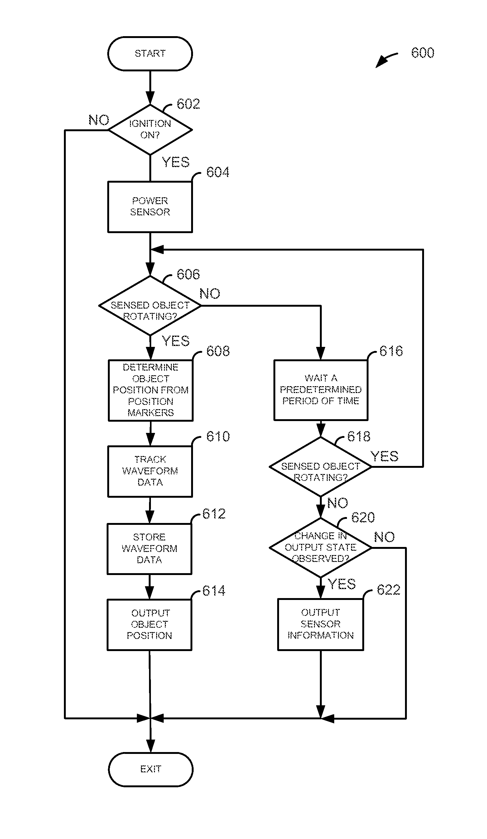
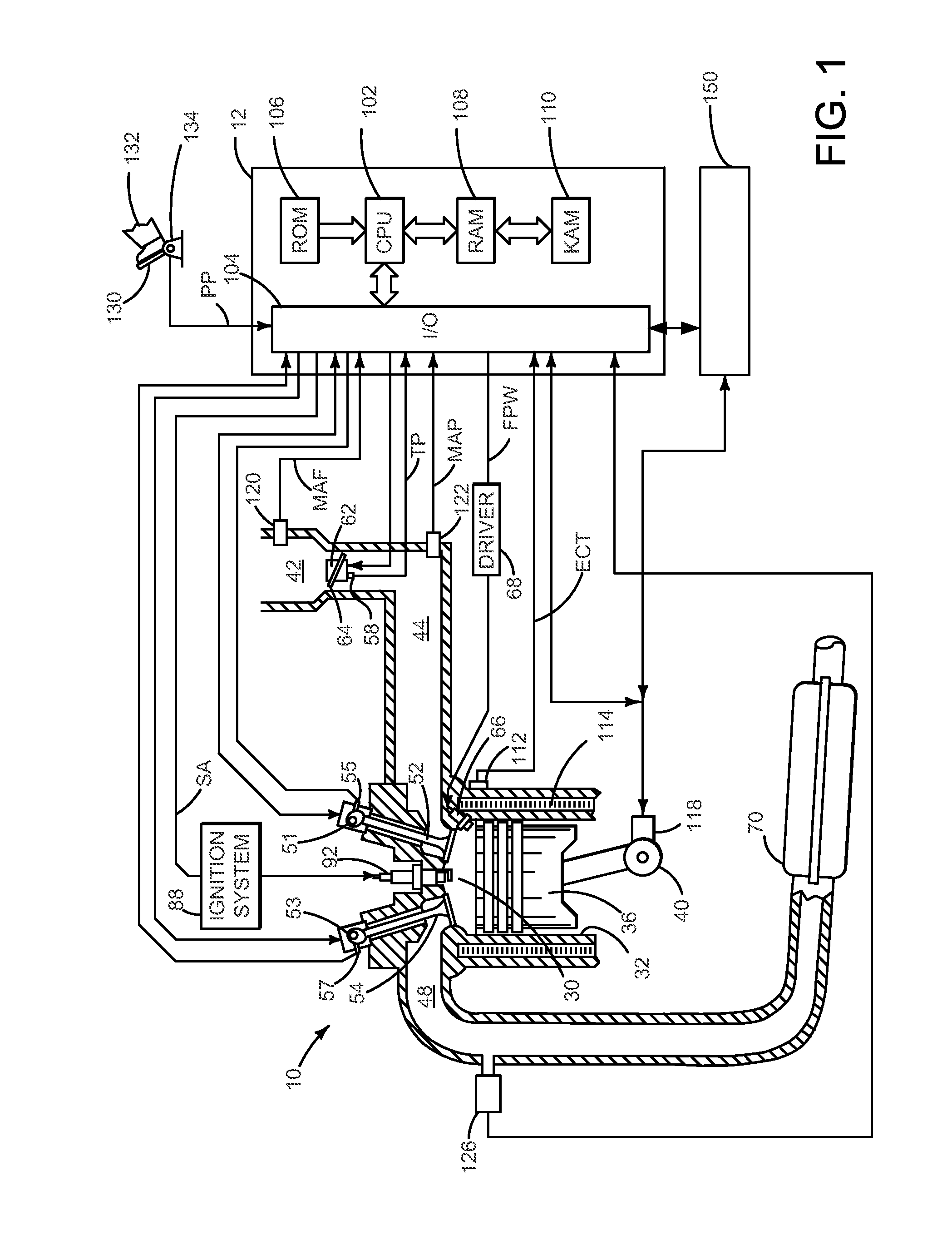
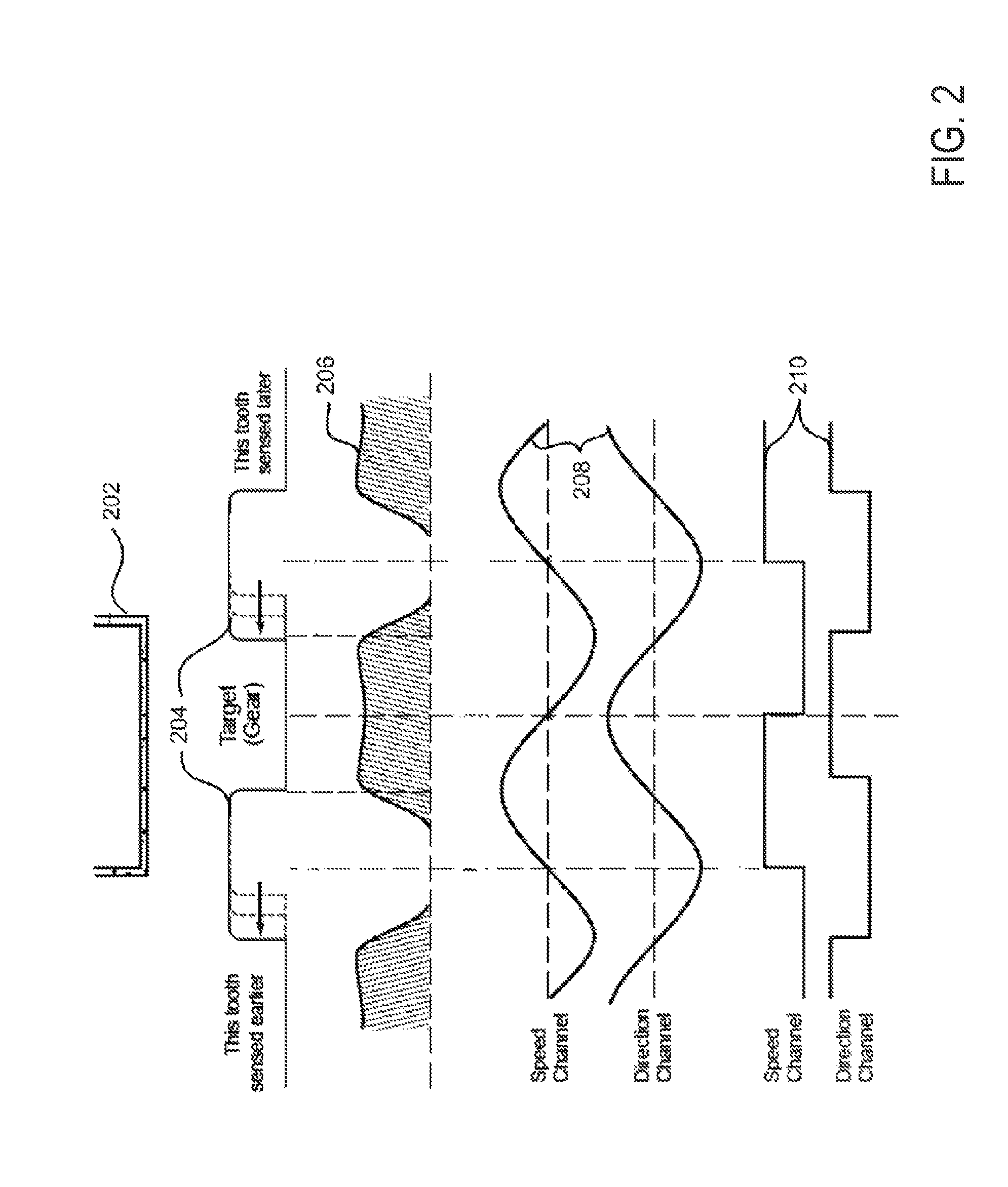
[0020]The present description is related to a sensor for determining the quality of a magnetic sensor profile. In one non-limiting example, FIG. 1 shows an advanced position sensor within an engine system. FIG. 2 shows an example magnetic sensor profile and signals within the advanced position sensor when a position of an engine is sensed, for example. The quality of the magnetic sensor profile may be output to an external system or controller as illustrated in FIG. 3 by the circuitry shown in FIG. 5. The sensor data is available to an external system after sensing a position of an object as shown in FIG. 4. provides an example data output sequence from and advanced position sensor. The position sensor and the external controller receiving position sensor information may be operated according to the methods of FIGS. 6 and 7.

[0021]Referring to FIG. 1, internal combustion engine 10, comprising a plurality of cylinders, one cylinder of which is shown in FIG. 1, is controlled by electro...


PUM


Abstract

A method for improving a position sensing system which measures a rotating object is presented. In one embodiment, the method outputs the position of the rotating object while the object is rotating, and the method follows an external command on the sensor output line when the object is not rotating to output information other than the position information.

Description

FIELD[0001]The present description relates to a system for improving the determination of a quality of a rotary position sensing system. The system may be particularly useful to ensure that a specific production assembly has been built properly or to diagnose degraded sensor systems in the field.BACKGROUND AND SUMMARY[0002]Accurate and reliable position information related to rotating objects is desirable for many applications. For example, engine position information can be important to operate an engine with low emissions and high efficiency. In particular, by knowing an accurate engine position, it is possible to precisely time fuel injection and spark as well as provide proper emissions monitoring through high level functions such as misfire detection by instantaneous speed misfire methods. Therefore, it is desirable to assure that a position sensing system has sufficient operating margin to provide proper position information over potential operating conditions including vibrat...

Claims


Application Information

Patent Timeline
Patent Type & Authority Patents(United States)
IPC IPC(8): G01C19/24G06F19/00G01C25/00
CPCG01B7/30G01D5/145G01D18/00
Inventor GOODWIN, WILLIAM RUSSELL
Owner FORD GLOBAL TECH LLC
Why Eureka
Try Eureka