Blister package opener

a blister package and opener technology, applied in the field of cutting tools, can solve the problems of two layers together, one packaging form, merchandise, and is exceptionally difficult to open, and achieve the effect of simple and reliable construction

Active Publication Date: 2013-05-21
FISHER STEPHEN
View PDF49 Cites 8 Cited by
  • Summary
  • Abstract
  • Description
  • Claims
  • Application Information

AI Technical Summary

Benefits of technology

[0008]With this invention a blister package opener is provided which avoids the relatively high exertion requirements and unpredictable operation associated with a scissors-like cutter or a razor blade. Instead, a pair of cutters are provided which are generally circular in form and which come together at an engagement area. At least one of the cutters rotates, and preferably both. This rotation causes layers of the blister package material, or other item placed within the engagement area, to be fed between the two cutters. The engagement area has a spacing between the two cutters which is less than a thickness of the layers of the blister package material or other item to be cut. Hence, the layers of material cannot merely bend and pass between the two cutters.
[0009]At least one of the pair of cutters is provided with a knife edge. Thus, the cutters rotate relative to each other and the edge of the blister package material is brought into the engagement area between the two cutter pairs, the cutters both draw the material into the engagement area and the knife on at least one of the cutters cuts the blister package material. Because the cutters act in a rotating fashion, advancement of the blister package material into the engagement area and through the cutters does not occur any faster than a rate associated with a speed of rotation of the cutters, and thus occurs in a highly controlled fashion.
[0010]Most preferably, both of the cutters rotate, and rotate together in opposite directions, tending to exert a feeding action to draw the blister package material, or other material being cut, into the engagement area. Preferably, one of the cutters has the circular knife thereon with the other cutter having a circular reference surface. This reference surface is preferably flat and in a substantially common plane with a flat side of the knife edge of the other cutter. Most preferably, the reference surface and the knife edge are in a common plane so that they are just touching each other, or only very slightly spaced from each other to avoid wear of the knife edge. A width of any such gap is preferably less than that of a single layer of the blister package material or other material to be cut.
[0013]To use the opener, a user merely needs to feed an edge of the blister package or other objects to be cut into the engagement area between the two cutters and either press the trigger or turn the hand crank. The cutters then feed the blister package material into the engagement area and proceed to cut the blister package material, typically along a straight cut line, along an entire substantially straight path through the blister package material. This cut path is typically selected to avoid the merchandise and void area between the two layers, such as along and parallel with one substantially straight edge of the blister package material. After the cutter has exited a second edge of the blister package material, an entire edge of the blister package material has been separated and the two layers of blister package material can be easily opened to access the merchandise between the two layers.Objects of the Invention
[0016]Another object of the present invention is to provide a tool which can open a blister package or other thin planar object safely and easily.
[0020]Another object of the present invention is to provide a blister package opener which is of a simple and reliable construction.

Problems solved by technology

One form of packaging, which while convenient for display and containment of merchandise, is exceptionally difficult to open.
While such strong securement of the layers is beneficial from a security standpoint, and to keep contents of the blister package from being damaged, lost or tampered with, such as within a store or other retail location; this strong bonding of the two layers together presents a serious challenge to one who wishes to open the blister package.
Prior art systems for opening such packages are known, but have been less than satisfactory.
However, the strength of the plastic material and its overall thickness make the user of scissors largely ineffective.
When rather high strength scissors, approaching the strength of tin snips or other shears, are utilized, some effectiveness can be achieved, but the overall process is cumbersome and still requires a rather large amount of force to bring the jaws of the scissors together.
When such high forces are being manually applied to the scissors, a great propensity exists to have the package open quickly and unexpectedly, and then have hands of a user move rapidly past the freshly cut edges of the packaging, creating the significant possibility of cutting hands of the user with the edges of the packaging, or the scissors.
Also, such high force opening tools pose a risk of damaging the merchandise.
Razor blades have a tendency to cut more than the packaging, including doing damage to an underlying surface.
Also, razor blades are exceptionally sharp and pose a risk to the user and to the merchandise within the packaging.
As with scissors, rather high forces are still required to utilize a razor blade to cut the layers of the blister package, again increasing the possibility that the package might open abruptly and cause the user to be cut either by a freshly cut edge of the package or by the razor blade itself.
While such attempts have generally improved upon the use of standard scissors or razor blades, the forces are still applied at a sufficiently high level and with sufficiently abrupt action, that difficulties are still encountered when utilizing such known prior art devices.

Method used


Image

  • Blister package opener
  • Blister package opener
  • Blister package opener

Examples


Embodiment Construction

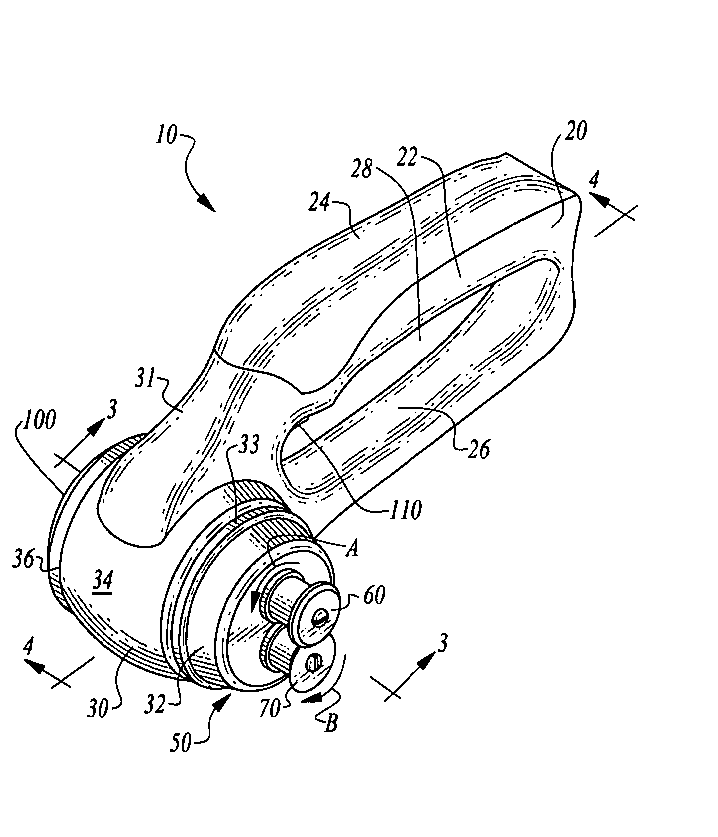
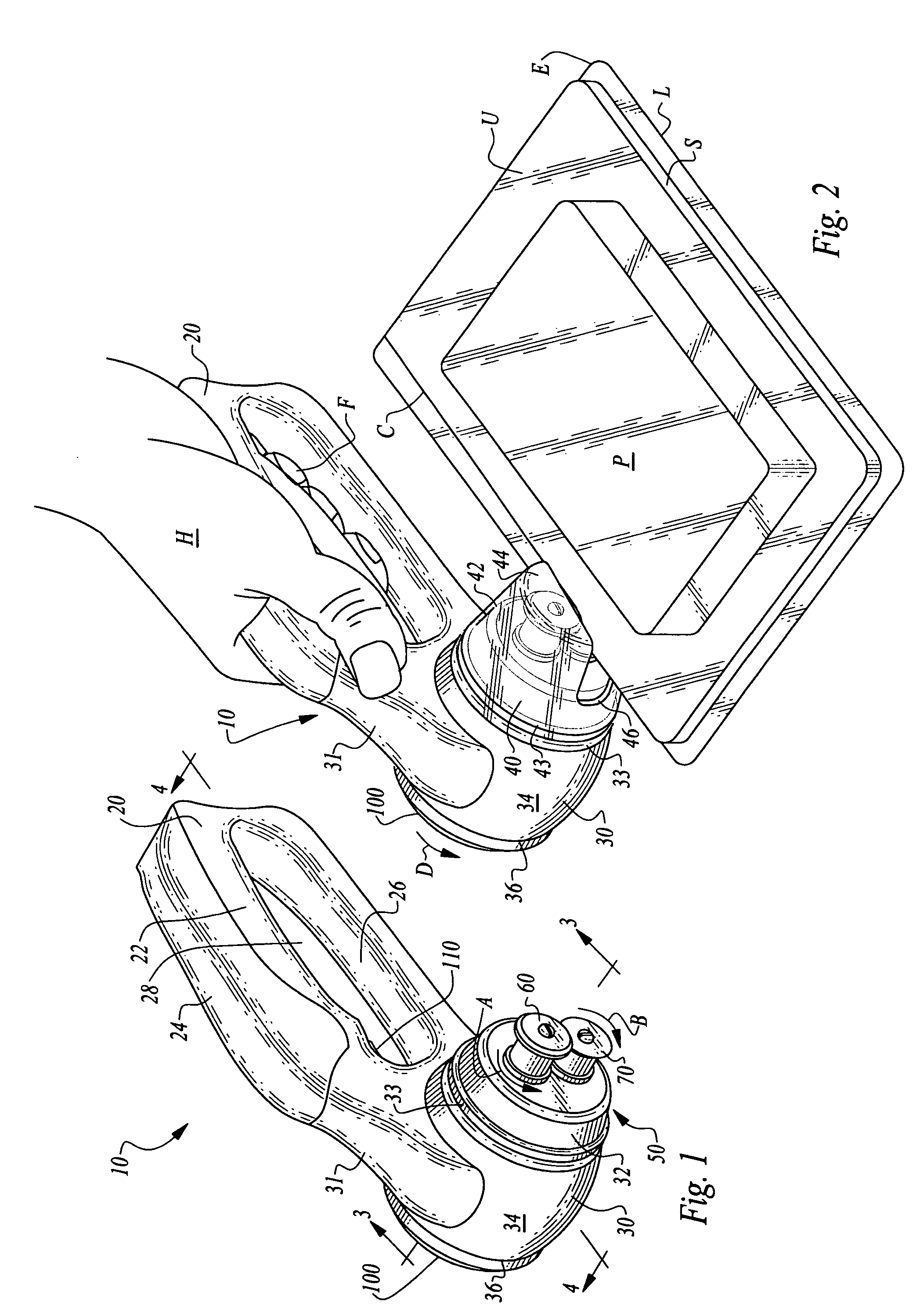
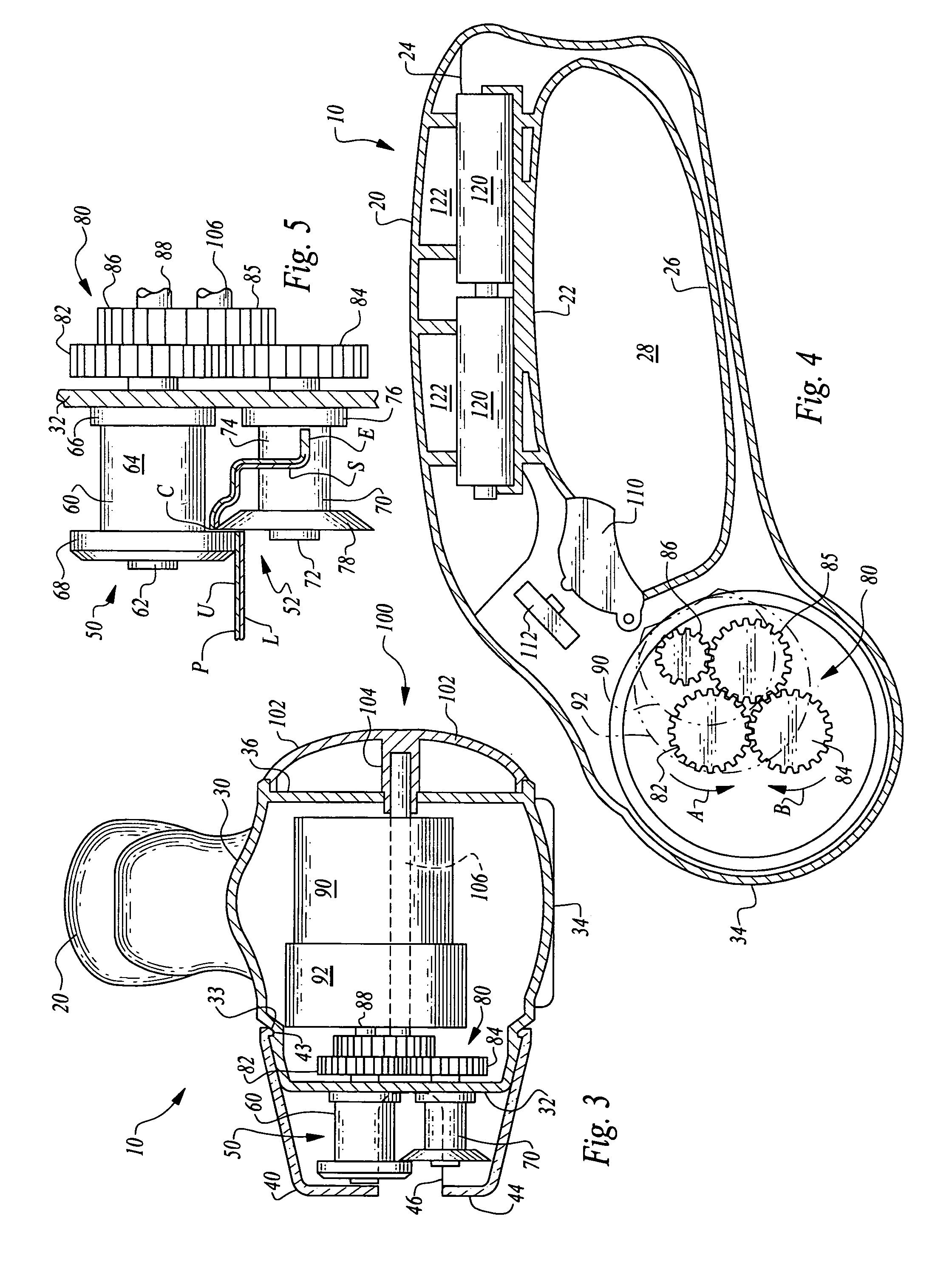
[0027]Referring to the drawings, wherein like reference numerals represent like parts throughout the various drawing figures, reference numeral 10 (FIG. 2) is directed to an opener for opening a blister package P or other related package, or for otherwise cutting generally planar material. The opener 10 has a cutter pair 50 (FIG. 5) which receives an upper layer U and lower layer L of the package P within an engagement area 52 between the cutters 60, 70 (FIG. 1). The cutters 60, 70 act together to cut through an edge E of the packaging P and along a cut line C (FIG. 2). The cutting procedure occurs at a rate matching a rate of rotation of the cutters 60, 70 controlled by a motor 90 or a hand crank 100 (FIG. 3), such that relatively minimal forces are applied in a controlled fashion to open the blister package P or otherwise cut planar material.

[0028]In essence, and with particular reference to FIGS. 1 and 2, basic details of the opener 10 of this invention are generally described ac...


PUM


Abstract

An opener for a blister package or for cutting of other planar material is disclosed. A cutter pair is provided adjacent an engagement area. When blister package layers are fed into the engagement area, the cutter pair including a top cutter and bottom cutter rotate to feed the package material through the engagement area. The cutters are closer together than a thickness of the package. At least one of the cutters includes a knife thereon to cause cutting of the material as it is fed between the cutter pair. A handle is provided supporting a head which has the cutter pair thereon. A motor provides power to cause rotation of the cutter pair through a gear set. A hand crank is also provided which can separately deliver power to the gear set to cause the cutters to rotate.

Description

FIELD OF THE INVENTION[0001]The following invention relates to cutters and other devices for cutting of planar articles and particularly packaging, such as plastic polyethylene blister packaging. More particularly, this invention relates to cutters which are dynamic in form including moving elements to achieve cutting of the material such as packaging material.BACKGROUND OF THE INVENTION[0002]One form of packaging, which while convenient for display and containment of merchandise, is exceptionally difficult to open. This packaging is referred to as blister packaging or as a “blister package.” With such blister packaging, two layers of plastic material (typically at least partially clear, and formed of polymeric hydrocarbon material, such as polyethylene) make up the package. These two layers are generally parallel to each other and come together at an edge where they terminate together. Heat, sonic welding, adhesive or other coupling secures the two layers together at this edge. Wit...

Claims


Application Information

Patent Timeline
Patent Type & Authority Patents(United States)
IPC IPC(8): B26B7/00B26B13/06B26B15/00
CPCB26B15/00B26B25/00B65B69/0033
Inventor FISHER, STEPHEN
Owner FISHER STEPHEN
Why Eureka
Try Eureka