Device for the forced locking of two elements oriented orthogonally to one another

Active Publication Date: 2013-05-21
METALSISTEM
View PDF13 Cites 1 Cited by
  • Summary
  • Abstract
  • Description
  • Claims
  • Application Information

AI Technical Summary

Benefits of technology

[0008]A further object of the invention is to provide the users with a device for the forced locking of two elements oriented orthogonally to o

Problems solved by technology

However, it has been found that this type of locking does not exclude the possibility of forming even little clearances over time and due to strains, between the tubular bodies; especially in crosswise direction, at the conical zone close to the coupling pin head, the thrust of a tubular body on the other is less than what occurs at the opposite conical zone, wherein said pin rests on a larger surface.
In a b

Method used


Image

  • Device for the forced locking of two elements oriented orthogonally to one another
  • Device for the forced locking of two elements oriented orthogonally to one another
  • Device for the forced locking of two elements oriented orthogonally to one another

Examples


Example

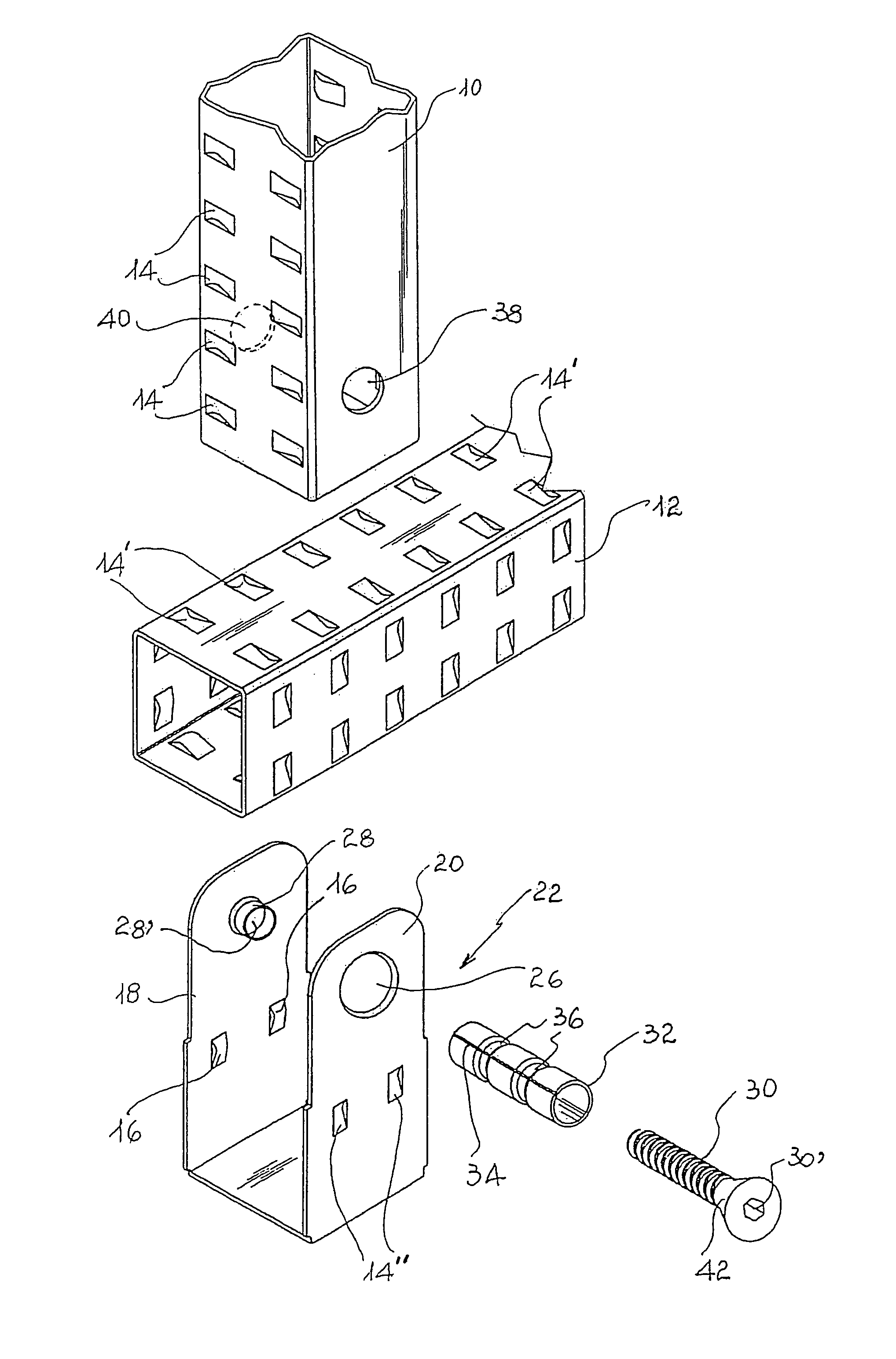
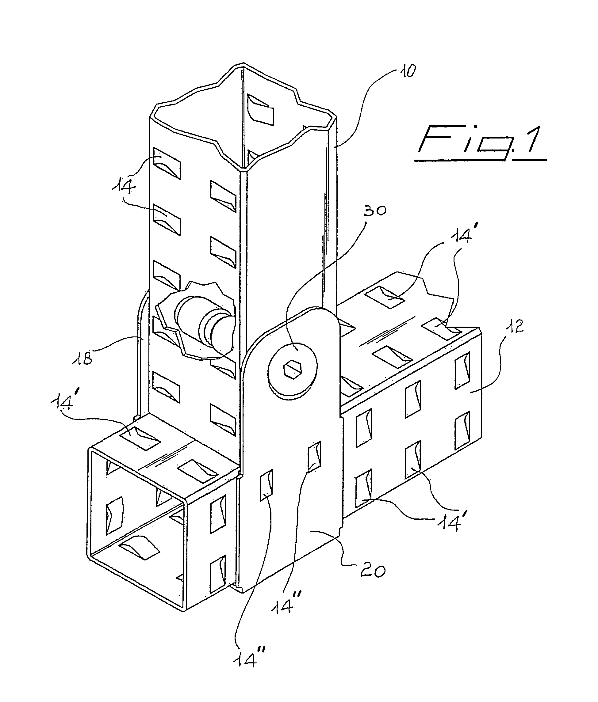
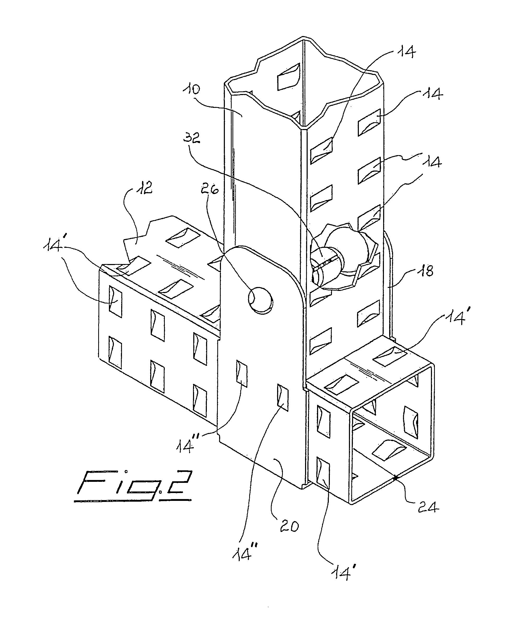
[0017]With reference to said figures, the forced locking device of the present invention is applied to two metal tubular elements oriented orthogonally to one another and partly delimited by a “U” shaped band, as described in EP 1,516,559.

[0018]Said tubular elements, respectively indicated with reference numerals 10 and 12, exhibit a quadrangular section and are in fact provided, along the faces that constitute the side surface thereof, with a plurality of shaped recesses 14 and 14′, respectively, wherein complementary projections 16 engage, which develop along the inner faces of the opposite and parallel branches 18, 20 of each “U” shaped band, globally schematised with reference numeral 22 in FIG. 3. The shaped recesses 14, 14′ and projections 16 are obtained by moulding the sheet, prior to the bending thereof, which gives rise to the quadrangular section, and prior to the longitudinal welding of the section bar, schematised with reference numeral 24 in FIG. 2. Substantially, rece...


PUM


Abstract

A device for the forced locking of two elements oriented orthogonally to one another, especially suitable for steadily connecting and constraining two tubular elements (10), (12) with quadrangular or polygonal section which are partly delimited by a U-shaped band (22) and which have, on at least one face, a plurality of pairs of shaped recesses (14), whereas the band (22) is correspondingly provided with pairs of complementary projections (16) developed projecting on the inner front of the opposite vertical and parallel branches (18) and (20) thereof. The device further includes a bush (32), extending between the branches (18) and (20) of band (22) and fitted, at one end, on a collar (28) which develops projecting along the inner front of branches (18) and (20), whereas the opposite end of bush (32) constitutes the inlet for a screw (30) the end whereof engages in a threaded hole (28′) delimited by the collar (28), bush (32) being extended transversally in the tubular element (10) or (12), provided with aligned holes (38), (40) along two opposite faces, starting from a hole (26) of the band (22).

Description

BACKGROUND OF THE INVENTION[0001]The present invention relates to a device for the forced locking of two elements oriented orthogonally to one another.[0002]More in particular, the present invention relates to a device as defined above, wherein the elements oriented orthogonally to one another consist of metal tubular bodies with a quadrangular or polygonal section, which on at least two faces are delimited by a “U” shaped band, equally made of metal. Said tubular bodies comprise, on at least two opposite faces, a plurality of pairs of shaped recesses, suitably spaced from one another, wherein corresponding projections made on the “U” bands abut. A solution of this type, intended for creating modular shelving wherein said tubular bodies are oriented orthogonally to one another, is also known from EP 1,516,559 by the same applicant, and comprises a shaped pin that is inserted crosswise into one of the tubular bodies for fixing the band. Said pin comprises opposite conical zones that ...

Claims


Application Information

Patent Timeline
IPC IPC(8): F16B1/00
CPCA47B47/021F16B12/40Y10T403/7058Y10T403/42Y10T403/4966Y10T403/4949Y10T403/557Y10T403/452F16B2200/67
Inventor BRIOSI, ANTONELLO
Owner METALSISTEM
Why Eureka
Try Eureka