Method and system for detecting epileptogenesis

a detection method and epileptogenesis technology, applied in the field of epileptogenesis detection methods and systems, can solve the problems of imbalance during the “latent period, unproved, functional implications, etc., and achieve the effect of easy synchronization

Inactive Publication Date: 2013-05-21
UNIV OF FLORIDA RES FOUNDATION INC
View PDF21 Cites 20 Cited by
  • Summary
  • Abstract
  • Description
  • Claims
  • Application Information

AI Technical Summary

Problems solved by technology

However, in vivo evidence of an emerging imbalance during the “latent period” between the initiation of injury and the expression of the first spontaneous behavioral seizure has not been demonstrated.
However, the functional implication of these synaptic changes leading to the progression of the brain to an epileptic state following brain injury in an in vivo system is still unknown.

Method used


Image

  • Method and system for detecting epileptogenesis
  • Method and system for detecting epileptogenesis
  • Method and system for detecting epileptogenesis

Examples


example

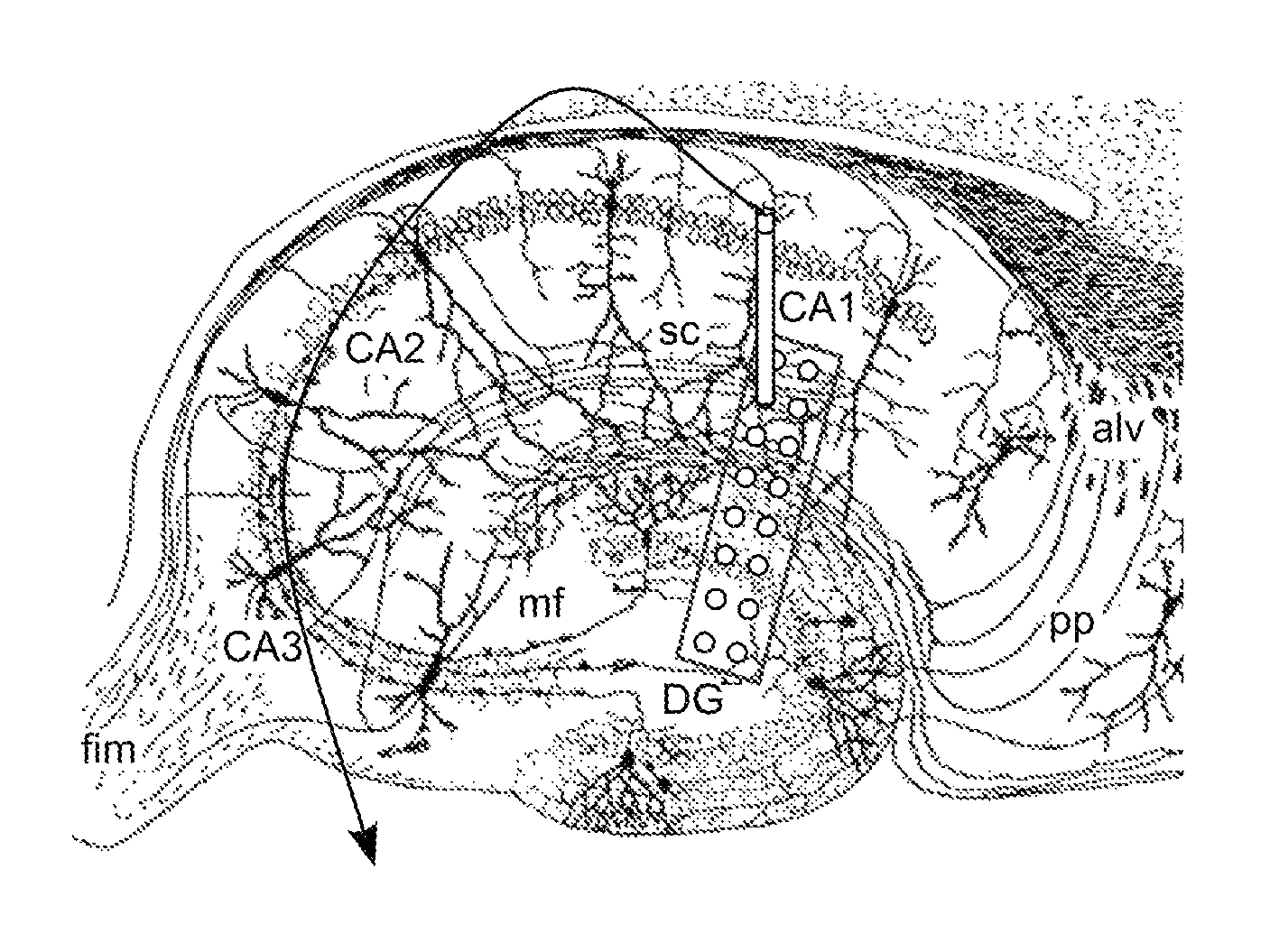
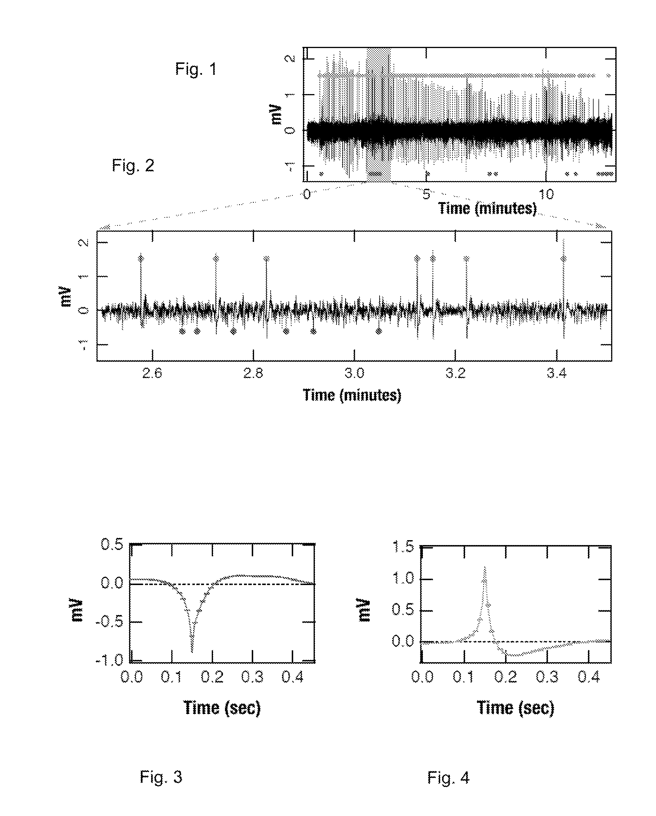
[0064]Local field potentials were recorded using a chronically implanted microwires (50 μm polyimide insulated tungsten) in the hippocampal CA1, CA2 and the dentate gyms. Out of a total of five rats, three rats were electrically stimulated into status epilepticus by injecting a bi-phasic current pulse through a bipolar twist stainless-steel electrode implanted in the ventral hippoampus. Continuous EEG / video data were collected at a high sampling rate of 12 KHz. In house software was used to save the recorded data in a 16-bit binary format for later processing. The schematic flow chart of the data analyzed to extract the excitatory and inhibitory field potentials is given in FIGS. 11A-G. All the figures were generated using custom programs within IGOR Pro (WaveMetrics, Inc).

[0065]Method Detail

[0066]The following method may be used for demonstrating biomarkers in accordance with the invention:

[0067]Animal Surgery and Electrode Implantation.

[0068]Experiments were performed on 2-months ...


PUM


Abstract

Neuronal excitation and inhibition of the brain is tracked in the hippocampal CA1 network during a latent period, wherein biomarkers are observed which include a sustained increase in the firing rate of the excitatory postsynaptic field activity, paired with a subsequent decrease in the firing rate of the inhibitory postsynaptic field activity; the mean amplitude profiles of both fEPSP and fEPSP field potential activity during the latent period have characteristic shapes; both excitatory and inhibitory CA1 field activity firing rates are observed to follow a circadian rhythm that drifts during epileptogenesis; the circadian rhythms described are in-phase in controls and anti-phase during epileptogenesis; and the fEPSP rate drifts from a circadian rhythm to a greater extent than the fEPSP rate. An additional biomarker is a change in a circadian rhythm of core body temperature. Therapeutic measures can include thermal, chemical, or electrical modulation, in an open or closed loop process.

Description

CROSS REFERENCE TO RELATED APPLICATIONS[0001]This application is a continuation-in-part of, and claims the benefit of, PCT Application PCT / US09 / 42452, filed Apr. 30, 2009, which in turn claims the benefit of U.S. Provisional Application Ser. No. 61 / 049,046, filed Apr. 30, 2008. The contents of each of the foregoing applications are hereby incorporated by reference in their entirety.STATEMENT REGARDING FEDERALLY SPONSORED RESEARCH, AND JOINT RESEARCH AGREEMENTS[0002]This research was supported by the National Institutes of Biomedical Imaging and Bioengineering (NIBIB) through Collaborative Research in Computational Neuroscience (CRCNS) Grant Numbers R01 EB004752 and EB007082, the Wilder Center of Excellence for Epilepsy Research, and the Children's Miracle Network. SST was partially funded by a Fellowship Grant from the Epilepsy Foundation of America. WLD was partially supported through the J. Crayton Pruitt Family Endowment funds. PRC was partially supported through the Wilder Cente...

Claims


Application Information

Patent Timeline
Patent Type & Authority Patents(United States)
IPC IPC(8): A61N1/00
CPCA61B5/0476A61B5/4094A61B2562/0209A61B2562/046A61B5/369
Inventor TALATHI, SACHIN S.HWANG, DONG-UKDITTO, WILLIAM L.CARNEY, PAUL R.SPANO, MARK
Owner UNIV OF FLORIDA RES FOUNDATION INC
Why Eureka
Try Eureka