Procedure for actuating a hydraulic parking brake

a technology of hydraulic clamping and parking brake, which is applied in the field of parking brakes, can solve the problems of increasing increasing the amount of hydraulic fluid inside the hydraulic chamber, so as to shorten the total duration of the parking brake operation, reduce the running time of the hydraulic actuator, and reduce the accompanying background nois

Active Publication Date: 2013-05-28
LUCAS AUTOMOTIVE GMBH
View PDF17 Cites 11 Cited by
  • Summary
  • Abstract
  • Description
  • Claims
  • Application Information

AI Technical Summary

Benefits of technology

[0010]In the course of the displacement of the brake piston by means of the mechanical actuator, a negative pressure which draws hydraulic fluid into the hydraulic chamber may be generated in the hydraulic chamber. In this way the hydraulic fluid volume inside the hydraulic chamber can be increased even without actuating the hydraulic actuator. The approach of increasing the hydraulic fluid volume inside the hydraulic chamber by means of the mechanical actuator in an initial phase of a parking brake operation therefore enables the running time of the hydraulic actuator, and the accompanying background noise, to be reduced.
[0011]After its initial activation to increase the hydraulic fluid volume contained in the hydraulic chamber, the mechanical actuator may be switched off and only reactivated in order to maintain (and optionally to further increase) a clamping force built up or increased hydraulically. It is also possible to operate the mechanical actuator permanently, or over a relatively long period, simultaneously with the hydraulic actuator. Thus, the mechanical actuator could remain activated throughout the operating phase of the hydraulic actuator. In such a case, however, the build-up of clamping force is advantageously effected by hydraulic means, while mechanically driven means of the mechanical actuator essentially merely follow rapidly behind the hydraulically actuated brake piston. Simultaneous operation of the mechanical and hydraulic actuators can shorten the total duration of the parking brake operation, since the mechanical actuator can, in particular, take over its holding function more quickly.

Problems solved by technology

The background noise accompanying the pump operation for hydraulically clamping the parking brake is often felt to be intrusive.
Although attempts have been made to mitigate the noise problem by decoupling the vibration from the vehicle, this measure has proved inadequate.
In that case, however, the pressure build-up requires more time, and during this (longer) time the pump operation noises are still clearly perceptible, even if somewhat reduced.

Method used


Image

  • Procedure for actuating a hydraulic parking brake
  • Procedure for actuating a hydraulic parking brake
  • Procedure for actuating a hydraulic parking brake

Examples


Embodiment Construction

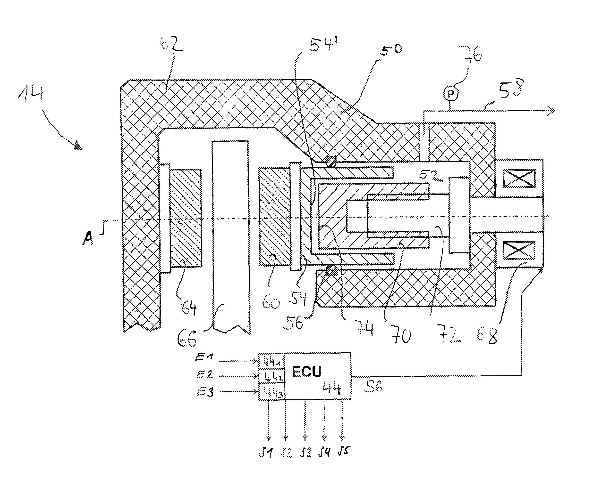
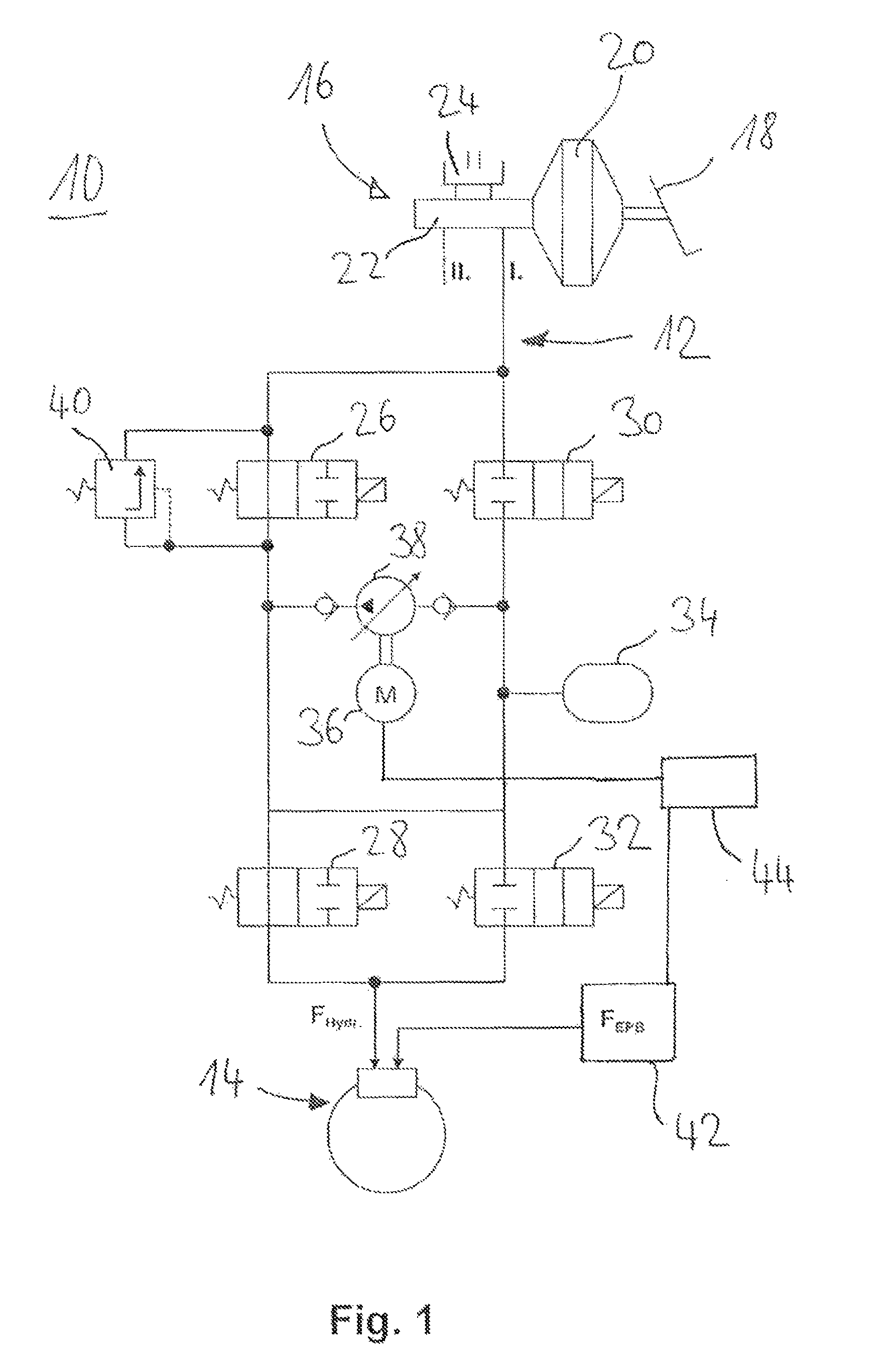
[0031]FIG. 1 shows an embodiment of a motor vehicle brake system 10 with hydraulic parking brake functionality. The brake system 10 comprises two separate brake or hydraulic circuits with a brake circuit split of the X-split type, for example, in which each front wheel and the opposite-side rear wheel of the motor vehicle are allocated to exactly one of the two brake circuits respectively. For simplicity, only a single brake circuit 12 with only a single wheel brake 14 is shown in detail in FIG. 1.

[0032]For service brake operations there is provided a brake pressure generating unit 16 configured in a conventional manner. The brake pressure generating unit 16 comprises a brake pedal 18, a brake servo 20, a master cylinder 22 coupled to both brake circuits and an unpressurised reservoir 24 for hydraulic fluid. In deviation from the embodiment represented in FIG. 1, in which the wheel brake pressure for service brake operations is generated by foot pressure, the invention could also be...


PUM


Abstract

A procedure for actuating a parking brake is described, the parking brake comprising a brake piston which is received in a hydraulic chamber and is displaceable within the hydraulic chamber by means of a hydraulic actuator on the one hand and a mechanical actuator on the other. During operation of the parking brake the mechanical actuator is activated in a first step in order to displace the brake piston in the hydraulic chamber in such a way that a volume of a hydraulic fluid contained in the hydraulic chamber is increased. At a subsequent time the hydraulic actuator is activated in order to build up or increase a clamping force of the parking brake. The hydraulically generated or increased clamping force is then maintained by means of the mechanical actuator.

Description

CROSS-REFERENCE TO RELATED APPLICATIONS[0001]This application is a national stage of International Application No. PCT / EP2008 / 010541 filed Dec. 11, 2008, the disclosures of which are incorporated herein by reference in entirety, and which claimed priority to German Patent Application No. 10 2008 012 338.2 filed Mar. 3, 2008, the disclosures of which are incorporated herein by reference in entirety.BACKGROUND OF THE INVENTION[0002]The invention relates generally to the field of parking brakes. In particular, the invention concerns parking brakes in which electric-motor driven hydraulic pumps are provided to build up a hydraulic pressure.[0003]Known from EP 0 996 560 A1, and corresponding U.S. Pat. No. 6,394,235 B1, both of which are incorporated by reference herein in entirety, is a hydraulic vehicle brake which can be operated both as a service brake and as a parking brake. When braking using the service brake, hydraulic fluid is introduced under pressure in a conventional manner in...

Claims


Application Information

Patent Timeline
Patent Type & Authority Patents(United States)
IPC IPC(8): F16D65/14
CPCB60T8/32B60T13/588B60T13/741B60T13/745B60T13/746
Inventor KNECHTGES, JOSEF
Owner LUCAS AUTOMOTIVE GMBH
Why Eureka
Try Eureka