Supported precious metal catalysts via hydrothermal deposition

a precious metal catalyst and hydrothermal deposition technology, which is applied in the direction of metal/metal-oxide/metal-hydroxide catalysts, physical/chemical process catalysts, other chemical processes, etc., can solve the problem of reducing the effective surface area and affecting the stability of precious metal catalyst particles

Active Publication Date: 2013-05-28
TRONOX LLC
View PDF59 Cites 11 Cited by
  • Summary
  • Abstract
  • Description
  • Claims
  • Application Information

AI Technical Summary

Benefits of technology

[0014]Thus, utilizing (1) the technology known in the art; (2) the above-referenced general description of the presently claimed and disclosed inventive concept(s); and (3) the detailed description of the invention that follows, the advantages and novelties of the presently claimed and disclosed inventive concept(s) would be readily apparent to one of ordinary skill in the art.

Problems solved by technology

A limitation of the prior art processes is that the particle size and size distribution of the supported precious metal catalyst particles cannot be tightly controlled.
Deposition is often within support pores which are not sufficiently exposed to controlled conditions.
Such secondary treatments typically also lower the degree of dispersion and thus, further reduce the effective surface area of the precious metal catalyst particles.

Method used


Image

  • Supported precious metal catalysts via hydrothermal deposition
  • Supported precious metal catalysts via hydrothermal deposition
  • Supported precious metal catalysts via hydrothermal deposition

Examples


example 1

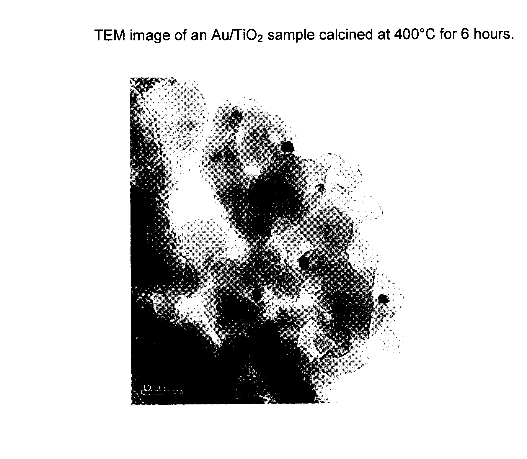
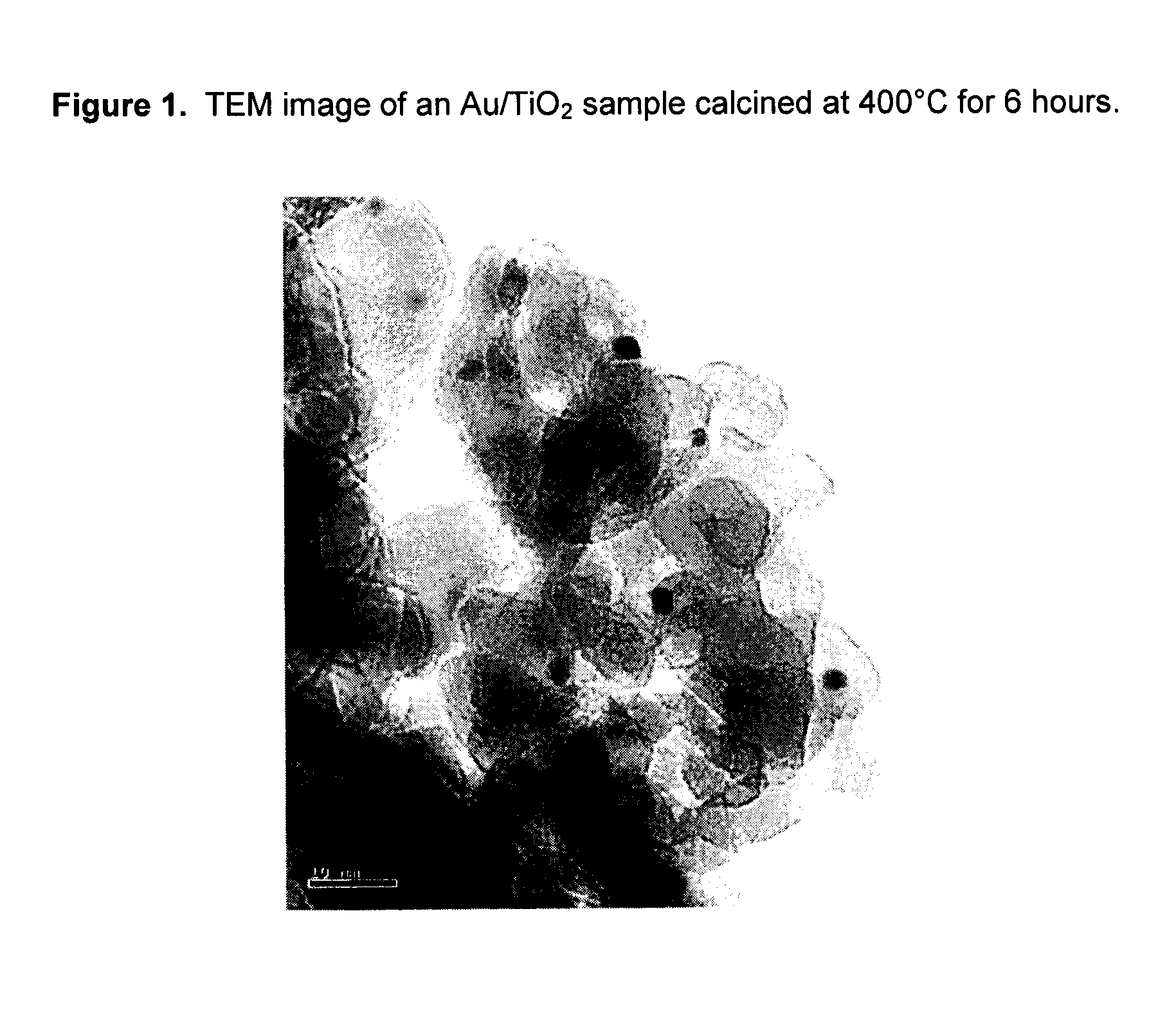
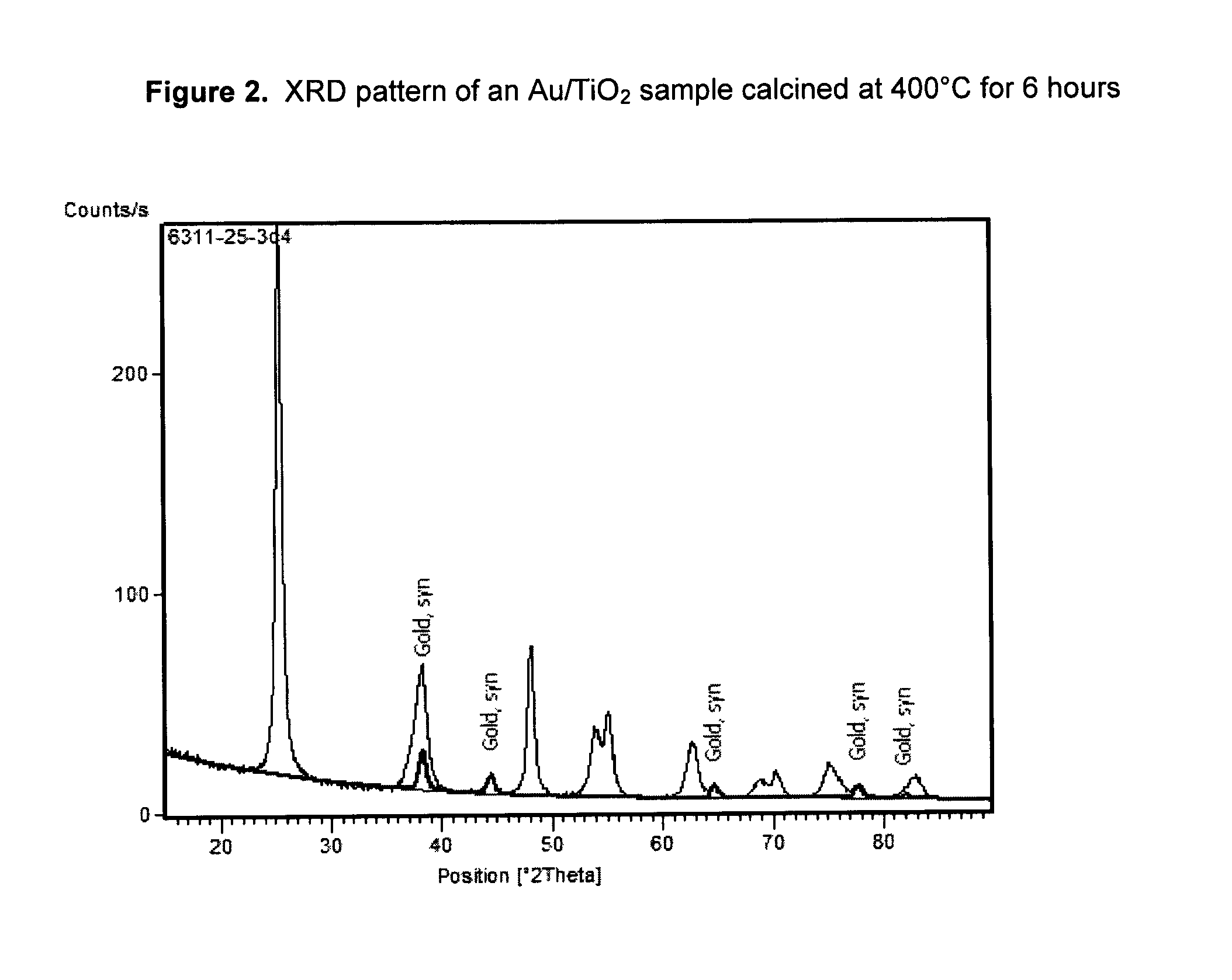
[0044]A 2 wt % gold catalyst on a TiO2 support was prepared by the following procedure. A slurry of Tiona® G1, an ultrafine TiO2 product made out of the so-called “sulfate process” by Millennium Inorganic Chemicals, was neutralized to pH 9 with an ammonia solution and washed thoroughly to remove the sulfate ions in the slurry. A sample of the washed Tiona® G1 containing 24 g TiO2 was then reslurried with 216 g of deionized water to make 10% TiO2 slurry. Separately, 0.97 g of NaAuCl4.2H2O (0.48 g of gold, Alfa Aesar) was dissolved in 40 g of deionized water, to which was added, in order, 20 g ethanol (Fisher, Reagent Grade) and 7 g stearic acid (99%, Alfa Aesar). The gold solution was stirred for about 15 minutes and was added to the TiO2 slurry prepared above. The Au / TiO2 mixture was stirred for another 15 minutes before transferring into three stainless steel bomb reactors lined with Teflon cups and lids (125 ml, Parr Instruments). The bomb reactors were put in a roller oven and th...

example 2

[0045]A 1 wt % platinum catalyst on TiO2 support was prepared by the same procedure as for Example 1, except that 0.57 g of Na2PtCl4.xH2O (O.24 g of platinum, Alfa Aesor) was used for platinum deposition. The platinum deposition was carried hydrothermally at 80° C. for 18 hours. A TEM image (FIG. 2) of a Pt / TiO2 sample calcined at 400° C. for 6 hours showed that Pt particles having an average particle size smaller than 5 nm were deposited on the surface of TiO2.

example 3

[0046]A 4 wt % silver catalyst on a TiO2 support was prepared by the same process as for Example 1, except that 1.5 g of AgNO3 (0.96 g of Ag, Alfa Aesor) was used for silver deposition. The deposition reaction was carried out under hydrothermal conditions at 90° C. for 18 hours. TEM measurement on a 400° C. calcined Ag / TiO2 sample indicated that silver particles having an average particle size smaller than 5 nm were deposited on the surface of TiO2.


PUM

PropertyMeasurementUnit
particle sizeaaaaaaaaaa
temperatureaaaaaaaaaa

Abstract

A process for making a catalyst having precious metal nanoparticles deposited on a support includes first providing an aqueous dispersion of support particles. A pre-treatment slurry is prepared by mixing the aqueous dispersion of support particles with a water-soluble precious metal precursor and a reducing agent. The pre-treatment slurry is hydrothermally treated at a temperature in the range of from about 40° C. to about 220° C. for a time sufficient to deposit precious metal nanoparticles on the surface of the support particles, the precious metal nanoparticles having an average particle size less about 50 nm.

Description

CROSS REFERENCE TO RELATED APPLICATIONS[0001]Not Applicable.STATEMENT REGARDING FEDERALLY SPONSORED RESEARCH OR DEVELOPMENT[0002]Not applicable.BACKGROUND[0003]1. Field of Invention[0004]The presently claimed and disclosed inventive concept(s) relates generally to catalysts and methods of making catalysts and, more particularly, but not by way of limitation, to catalysts and methods of making catalysts of precious metal nanoparticles supported on metal oxide particles.[0005]2. Background of the Invention[0006]Precious metal nanoparticles supported on metal oxides can provide active catalysts for a number of reactions of both environmental and industrial importance. For example, Rodriguez, et al. [1] teach that gold nanoparticles deposited on titania are active catalysts for the low-temperature oxidation of carbon monoxide, the selective oxidation of propene, and photocatalytic oxidations used for environmental cleanup.[0007]Supported precious metal catalysts are typically prepared b...

Claims


Application Information

Patent Timeline
Patent Type & Authority Patents(United States)
IPC IPC(8): B01J23/00B01J21/00B01J20/00
CPCB01J37/16B01J37/031B01J37/035B01J37/10B01J21/063B01J35/006B01J23/44B01J23/50B01J23/52B01J35/002B01J23/42Y02E60/50B01J23/38B01J23/40B01J37/02B01J37/08
Inventor FU, GUOYIWATSON, MARK B.MUEHLBERGER, CHARLES B.
Owner TRONOX LLC
Why Eureka
Try Eureka