
Wind turbine generator and tidal current generator and operation method thereof

a wind turbine and generator technology, applied in the direction of electric generator control, rotary clutches, fluid couplings, etc., can solve the problems of increased cost and heavy gearbox, and achieve the effect of improving power generation efficiency and constant rotation speed of the generator

Inactive Publication Date: 2013-05-28
MITSUBISHI HEAVY IND LTD
View PDF14 Cites 9 Cited by
  • Summary
  • Abstract
  • Description
  • Claims
  • Application Information

AI Technical Summary

Benefits of technology

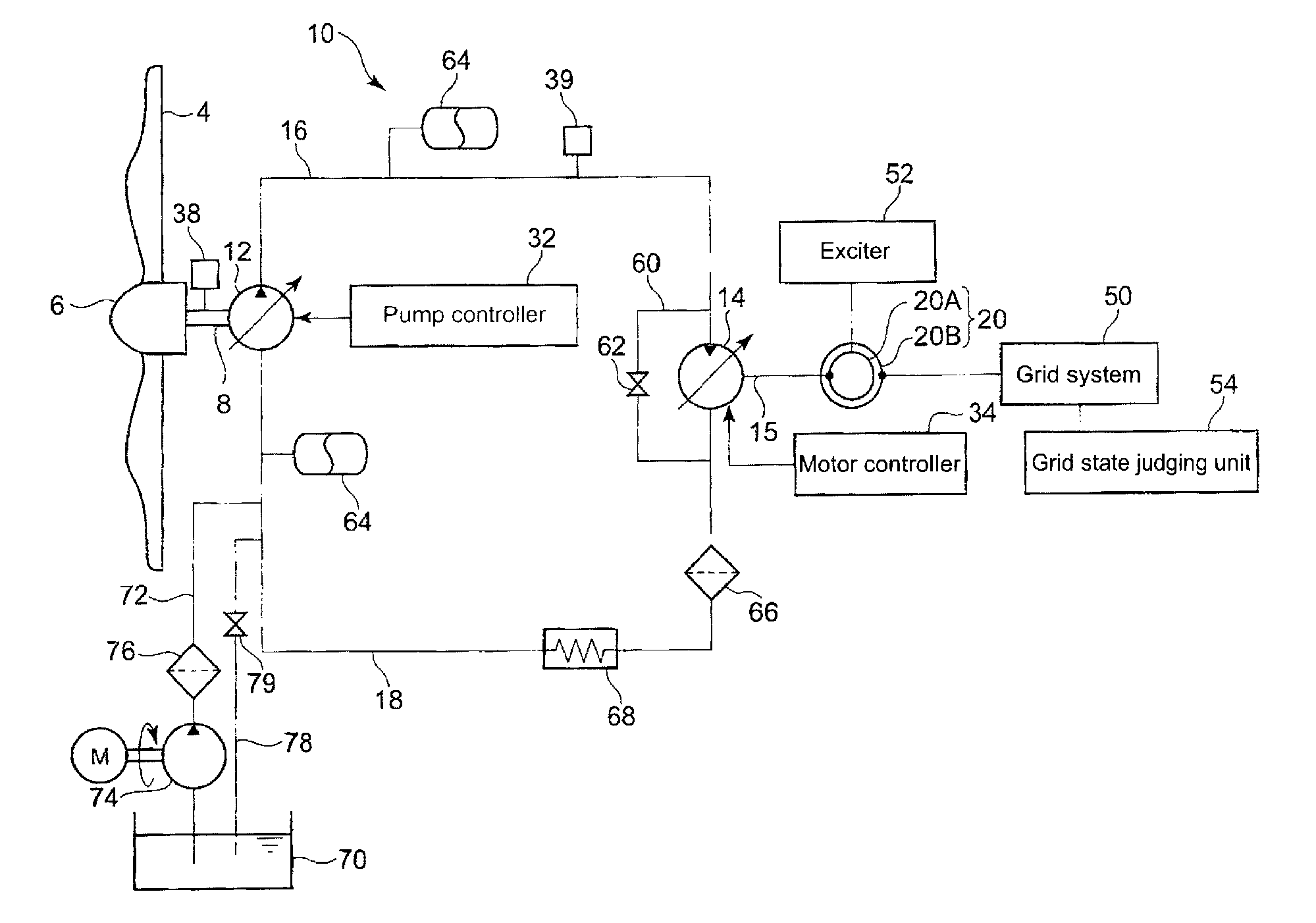
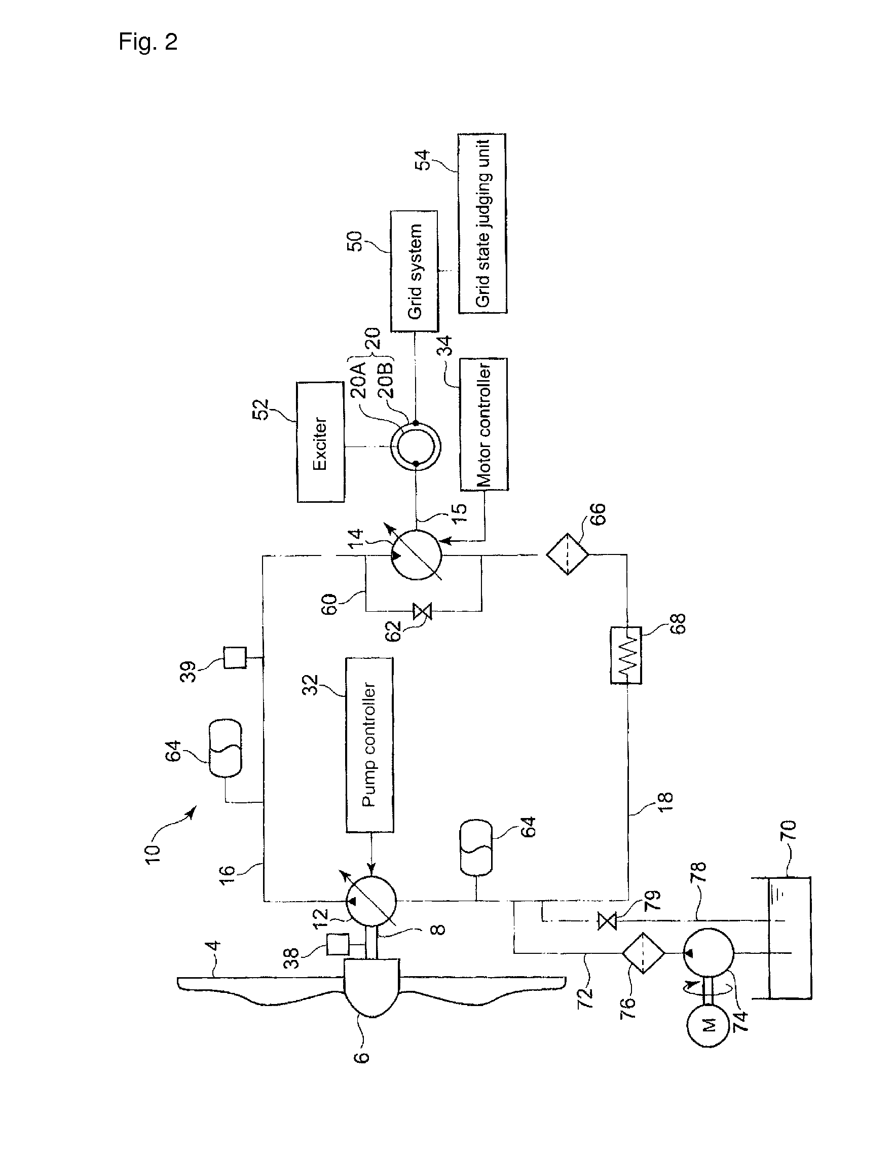
The present invention improves power generation efficiency by controlling the hydraulic pump based on the target torque and pressure of operating oil in the high pressure oil line. The displacement of the hydraulic pump is set to achieve a maximum power coefficient, and the displacement of the hydraulic motor is set to maintain a constant rotation speed. As a result, the generator can generate electric power with a constant frequency.

Problems solved by technology

In recent years, the gearbox tends to become heavier and more expensive as the wind turbine generators are getting larger to improve power generation efficiency.

Method used


Image

  • Wind turbine generator and tidal current generator and operation method thereof
  • Wind turbine generator and tidal current generator and operation method thereof
  • Wind turbine generator and tidal current generator and operation method thereof

Examples


Embodiment Construction

[0062]A preferred embodiment of the present invention will now be described in detail with reference to the accompanying drawings. It is intended, however, that unless particularly specified, dimensions, materials, shape, its relative positions and the like shall be interpreted as illustrative only and not limitative of the scope of the present.

[0063]A general structure of the wind turbine generator in relation to a preferred embodiment is explained hereinafter. As an example of the wind turbine generator, a three-bladed wind turbine is used. However, the preferred embodiment is not limited to this example and can be applied to various types of wind turbines.

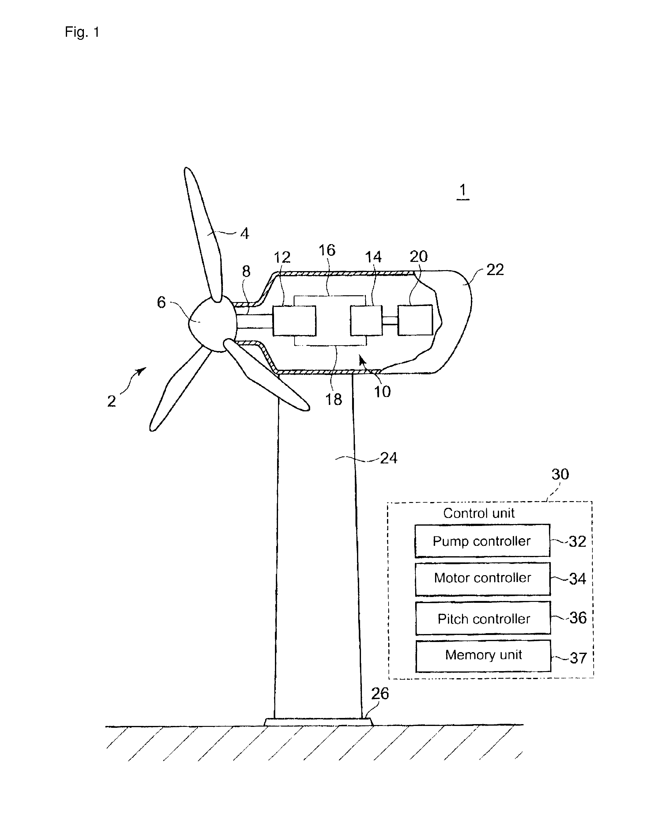
[0064]FIG. 1 is an illustration of an example structure of a wind turbine generator. FIG. 3 is an illustration of a structure of a pitch driving mechanism.

[0065]As illustrated in FIG. 1, a wind turbine generator 1 comprises a rotor 2 rotated by the wind, a hydraulic transmission 10 for increasing rotation speed of the rotor 2, a...


PUM


Abstract

An object of the invention is to provide a wind turbine generator or a tidal current generator which is equipped with a hydraulic transmission and achieves a superior power generation efficiency, and a operation method thereof. The wind turbine generator 1 comprises a hydraulic pump 12 of a variable displacement type which is rotated by the main shaft 8, a hydraulic motor 14 of a variable displacement type which is connected to the generator 20, and a high pressure oil line 16 and a low pressure oil line 18 which are arranged between the hydraulic pump 12 and the hydraulic motor 14. The pump controller 32 obtains a target torque of the hydraulic pump 12 at which a power coefficient becomes maximum, and then sets a displacement Dp of the hydraulic pump 12 based on the target torque and the pressure in the high pressure oil line 16. The motor controller 34 sets a displacement Dm of the hydraulic pump 14 based on a discharge amount Qp of the hydraulic pump obtained from the displacement Dp of the hydraulic pump 12 so that the rotation seed of the generator 20 becomes constant.

Description

RELATED APPLICATIONS[0001]The present application is national phase of, and claims priority from, International Application Number PCT / JP2010 / 006982, filed Nov. 30, 2010.TECHNICAL FIELD[0002]The present invention relates a wind turbine generator and a tidal current generator, which transmit a rotation of a rotor to a generator via a fluid transmission having a combination of a hydraulic pump and a hydraulic motor and an operation method of the wind turbine generator.BACKGROUND ART[0003]In recent years, from a perspective of preserving the environment, it is becoming popular to use a renewable energy type turbine generator such as a wind turbine generator utilizing wind power and a tidal current generator utilizing tidal current.[0004]Among the turbine generators, the wind turbine generator converts motion energy of the wind to the rotation energy of the rotor and further converts the rotation energy of the rotor to electric power by the generator. In a common wind turbine generator,...

Claims


Application Information

Patent Timeline
Patent Type & Authority Patents(United States)
IPC IPC(8): F03D9/00F03D9/28
CPCF03B13/264F16H61/47F03D9/001F03D11/02F16H61/421F03D7/028F05B2240/97F05B2260/406F05B2260/506F05B2270/20F05B2270/32Y02E10/722Y02E10/28Y02E10/723Y02E10/725F03D15/00F03D9/28F03D15/20Y02E10/72Y02P80/10Y02E10/30F05B2270/328Y02E10/20
Inventor TSUTSUMI, KAZUHISASHIMIZU, MASAYUKICALDWELL, NIALLDUMNOV, DANIILLAIRD, STEPHENPAPPALA, VENKATA
Owner MITSUBISHI HEAVY IND LTD
Learn More