
Electric vehicle having drivetrain and suspension

a technology of electric vehicles and suspensions, applied in the direction of crankshaft transmission, crankshaft mounting, cycles, etc., can solve the problem that the space above the swing arm cannot be used effectively

Inactive Publication Date: 2013-06-04
HONDA MOTOR CO LTD
View PDF35 Cites 13 Cited by
  • Summary
  • Abstract
  • Description
  • Claims
  • Application Information

AI Technical Summary

Benefits of technology

[0014]The electric vehicle described herein makes it no longer necessary to dispose the suspension in the space above the swing arm, and accordingly makes it possible to use the space above the swing arm effectively, because: the electric motor is connected to the drive shaft in a way that the electric motor is set in the longitudinal layout in which the rotating shaft is disposed in the front-rear direction of the vehicle, and in a way that the electric motor is disposed, deviated from the center to one of the left and right sides in the vehicle width direction; and the suspension is disposed under the electric motor and the drive shaft, and on the inner sides of the electric motor and the drive shaft in the vehicle width direction, with the position of the suspension in the front-rear direction overlapping the positions of the electric motor and the drive shaft in the front-rear direction. Moreover, it is possible to dispose the electric motor, the drive shaft and the suspension compactly in a collective manner in the front-rear direction and the vehicle width direction. In addition, since the electric motor is set in the longitudinal layout in which the rotating shaft is disposed in the front-rear direction of the vehicle, it is no longer necessary to employ a mechanism for converting the direction of the axis of rotation to the front-rear direction of the vehicle, and further reduction in size can be achieved. Additionally, since the suspension is disposed under the electric motor and the drive shaft, the suspension can protect the electric motor and the drive shaft from flying stones and something similar.
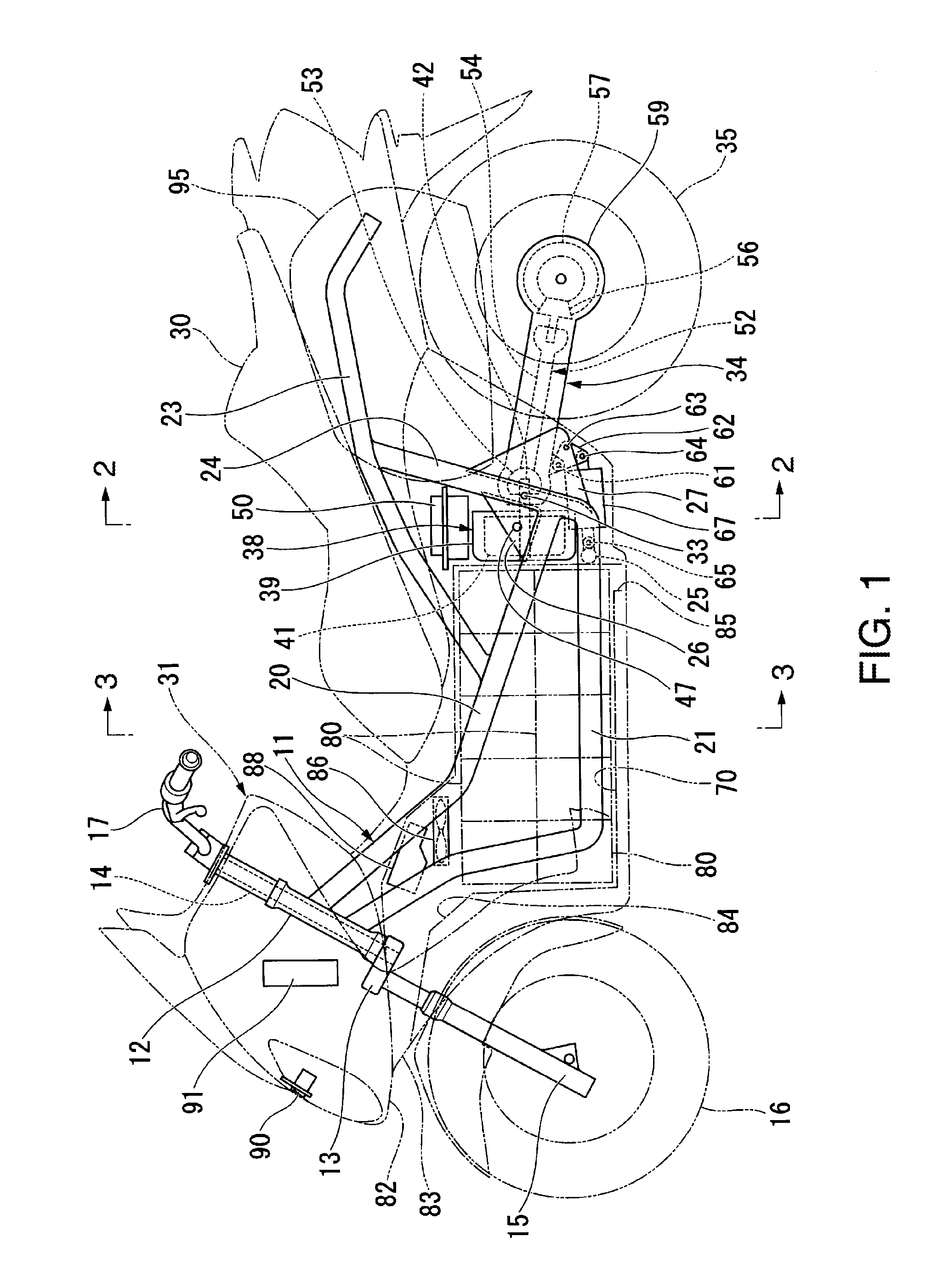
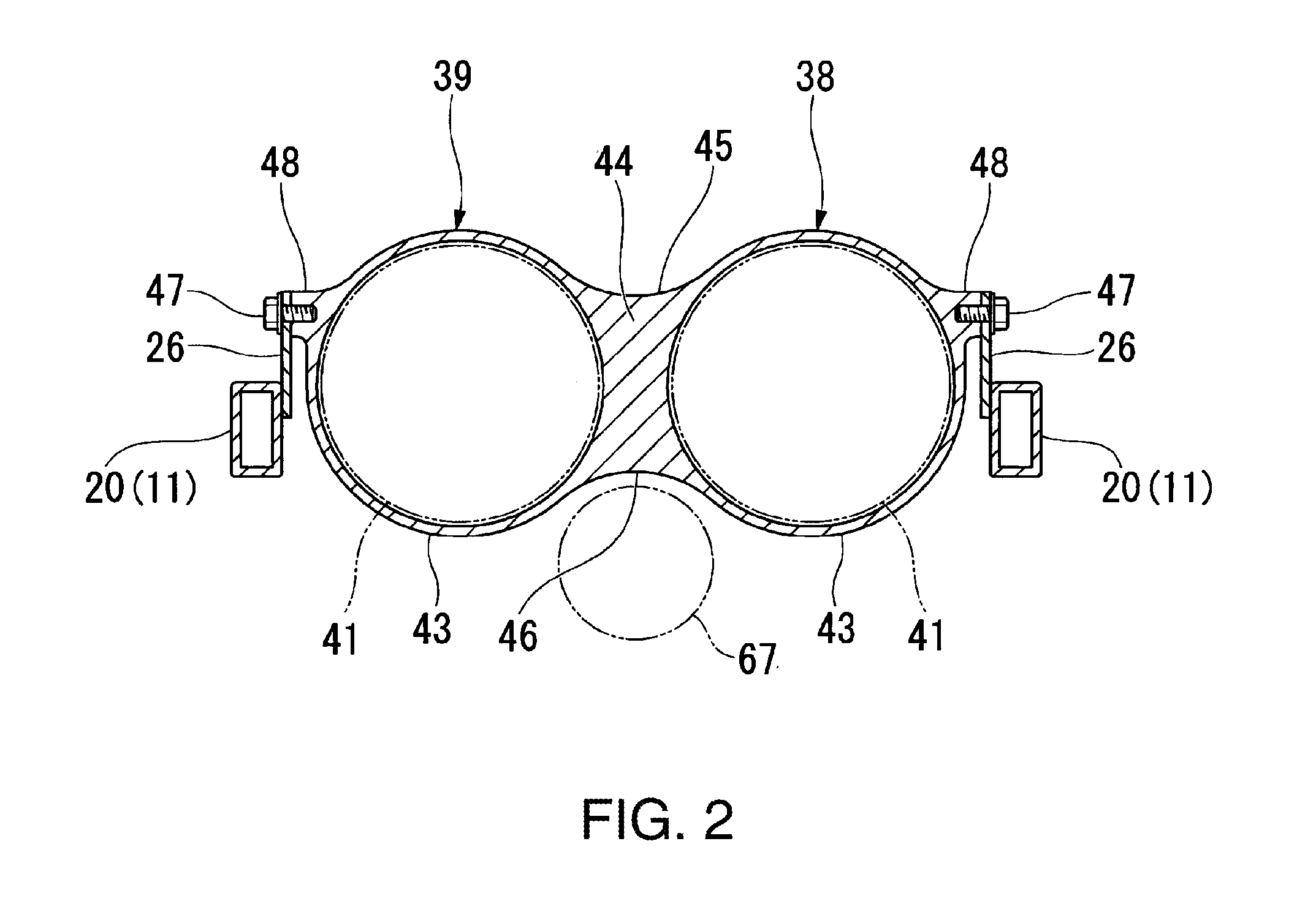
[0015]Additionally, the electric vehicle described herein makes it possible to achieve equalization of the weight balance by distributing the electric motors and the drive shafts, which are heavy articles, between the left and right sides, as well as by disposing the suspension therebetween, because: the sets of the electric motors and the drive shafts are disposed, respectively, on the left and right sides in the vehicle width direction in parallel; and the suspension is disposed between the sets. Moreover, it makes it possible to reduce the arrangement space in size, and thus to secure a wider space around the arrangement space, because the distribution of the electric motors and the drive shafts between the multiple sets enables reduction in size of the electric motor and the drive shaft which are included in each set.
[0016]Additionally, the electric vehicle described above makes it possible to secure a volume for the storage box, because the storage box is attached to the seat rail by disposing the storage box in the space portion on the lateral side of the seat rail above the swing arm or the drive shaft, or in the space portion between the swing arm or the drive shaft and the seat rail.
[0017]Further, it is possible to achieve reduction in the size of the vehicle body because the battery storage box is disposed by effectively using the space (straddle portion of the rider) among the upper frames and the lower frames. In addition, it is possible to secure the height for the battery storage box by disposing the electric motor in the rear of the battery storage box.
[0020]Still further it is possible to use the space in front of the electric motor effectively, because the drive shaft is that configured to transmit the driving force of the electric motor to the rear wheel.
[0021]Still further it is possible for the lower frames to prevent the bottom of the electric motor from hitting the road, because the position of the lower end of the electric motor is located above the location of the lower end of each lower frame.

Problems solved by technology

The structure in which the rear wheel suspension is disposed between the swing arm and the vehicle body frame above the swing arm as described above has a problem in that a space above the swing arm cannot be used effectively.

Method used


Image

  • Electric vehicle having drivetrain and suspension
  • Electric vehicle having drivetrain and suspension
  • Electric vehicle having drivetrain and suspension

Examples


first embodiment

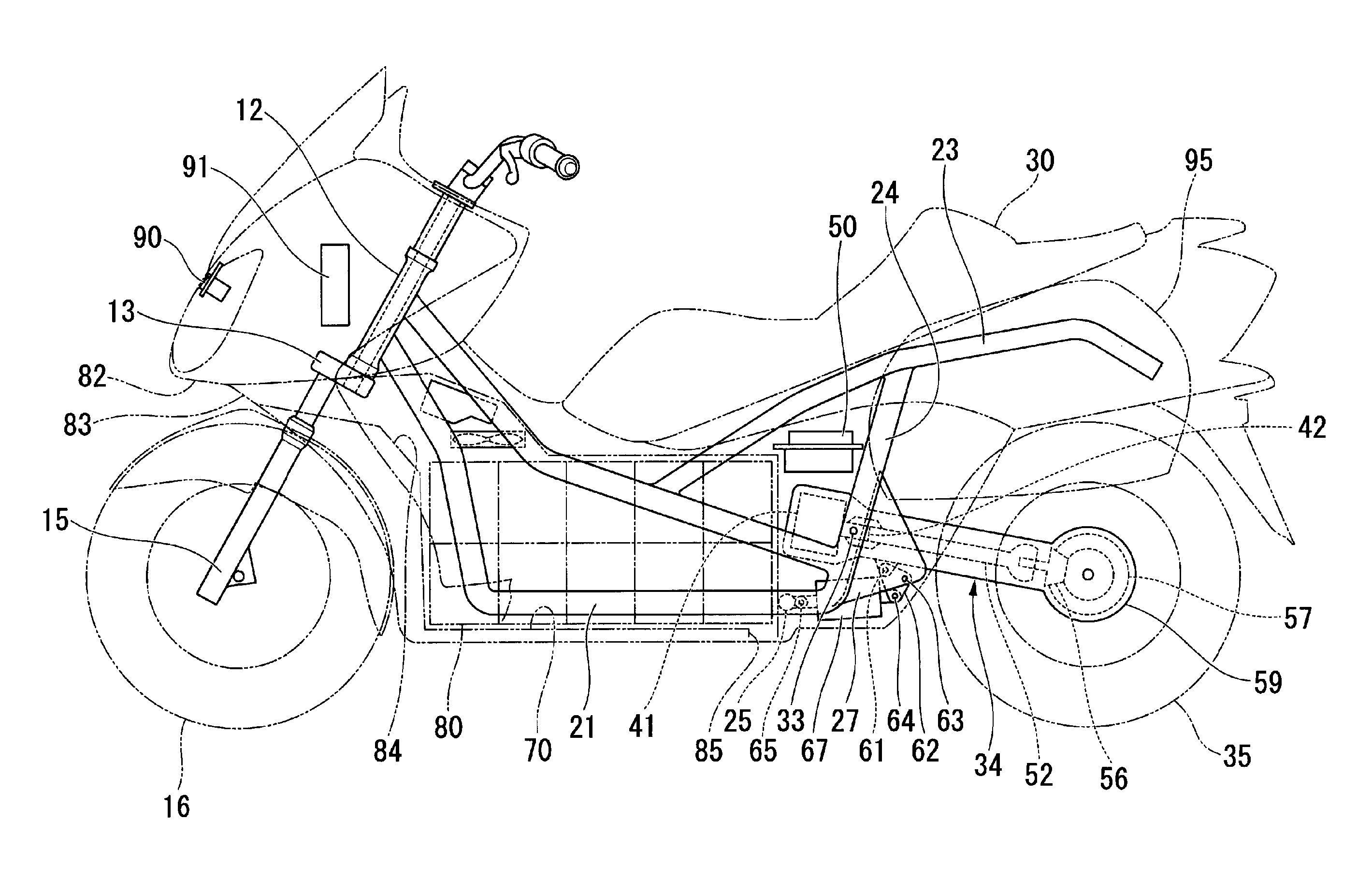
[0028]an electric vehicle is illustrated in FIG. 1 to FIG. 4.

[0029]The first embodiment of the electric vehicle is an electric motorcycle, and includes a vehicle body frame 11 forming the framework of the vehicle body as shown in FIG. 1. A steering shaft 14 provided to a stem 13 is rotatably pivotally supported by a head pipe 12 at the front end of the vehicle body frame 11. In addition, paired left and right front forks 15 are attached to the stem 13. A front wheel 16 is pivotally supported by the lower end portions of the respective front forks 15, and a handlebar 17 is attached to an upper portion on the stem 13. With this configuration, the front wheel 16 is steerable through manipulation of the handlebar 17.

[0030]In addition, the vehicle body frame 11 includes: paired left and right upper frames (main frames) 20 extending rearward, respectively, from the left and right of the upper portion of the aforementioned head pipe 12 on an upper side; and paired left and right lower fram...

second embodiment

[0065]The electric vehicle of the second embodiment as described above makes it possible to build the electric motors 41 and the swing arm 34 in a single unit, and thereby to improve the assembly workability, because the electric motors 41 swing integrally with the swing arm 34.

[0066]Note that, although the first and second embodiments have been described citing the case where the two electric motors 41 are provided, the invention can be applied to a case where only one electric motor 41 is provided.

[0067]In addition, although the first and second embodiments have been described citing the electric motorcycle, the invention can be applied to things such as an electric four-wheeled vehicle of a saddle riding type in which two rear wheels are supported by a swing arm.


PUM


Abstract

An electric vehicle includes a vehicle body frame; an electric motor; a swing arm pivotally supporting a rear wheel at a rear end thereof; a drive shaft for transmitting the driving force of the electric motor to the wheel; and a suspension connecting the vehicle body frame and the swing arm together. The electric motor is set in a longitudinal layout in which a rotating drive shaft is disposed in a front-rear direction of the vehicle; and is offset from a center to either of left and right sides in a vehicle width direction. The suspension is disposed under the electric motor and the drive shaft, and on the inner sides of the electric motor and the drive shaft in the vehicle width direction, and overlapping the positions of the electric motor and the drive shaft in the front-rear direction.

Description

CROSS-REFERENCE TO RELATED APPLICATION[0001]This application claims priority of Japanese Patent Application No. 2010-244335, filed Oct. 29, 2010, the entire contents of which are incorporated herein by reference.BACKGROUND OF THE INVENTION[0002]The present invention relates to an electric vehicle.[0003]Among vehicles having an electric motor for generating a travel driving force, some vehicles include a structure in which: a swing arm supporting a rear wheel is configured by a power unit including the electric motor; and a rear wheel suspension is disposed between the swing arm and a vehicle body frame above the swing arm as shown by Japanese Patent Application Publication No. Hei 11-79054.[0004]The structure in which the rear wheel suspension is disposed between the swing arm and the vehicle body frame above the swing arm as described above has a problem in that a space above the swing arm cannot be used effectively.[0005]A feature of the disclosed electric vehicle is to provide an...

Claims


Application Information

Patent Timeline
Patent Type & Authority Patents(United States)
IPC IPC(8): B60K6/42
CPCB62M7/12B62K2202/00B62K2204/00
Inventor KONDO, NOBUYUKIMATSUDA, JUNICHIYAMANAKA, TAKASUMIHONDA, NAOYOSHIKANAZAWA, IZUMISHIMURA, YUICHIRO
Owner HONDA MOTOR CO LTD
Learn More