Method and system for arranging link resource fragments
a technology of resource fragments and methods, applied in the field of optical communication, can solve the problems of resource fragment generation inevitably, and achieve the effect of maximizing the utilization of bandwidth resources
- Summary
- Abstract
- Description
- Claims
- Application Information
AI Technical Summary
Benefits of technology
Problems solved by technology
Method used
Image
Examples
first embodiment
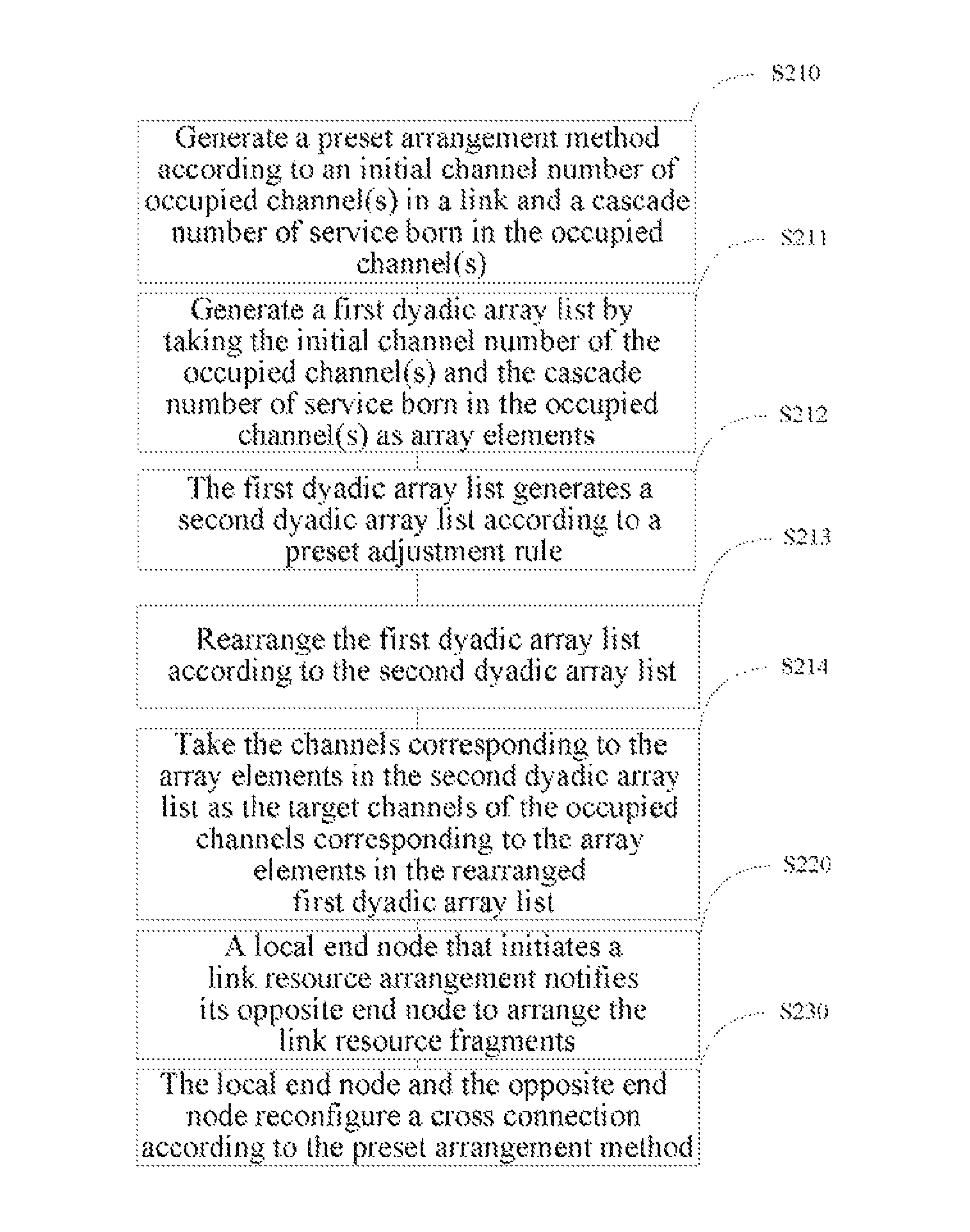
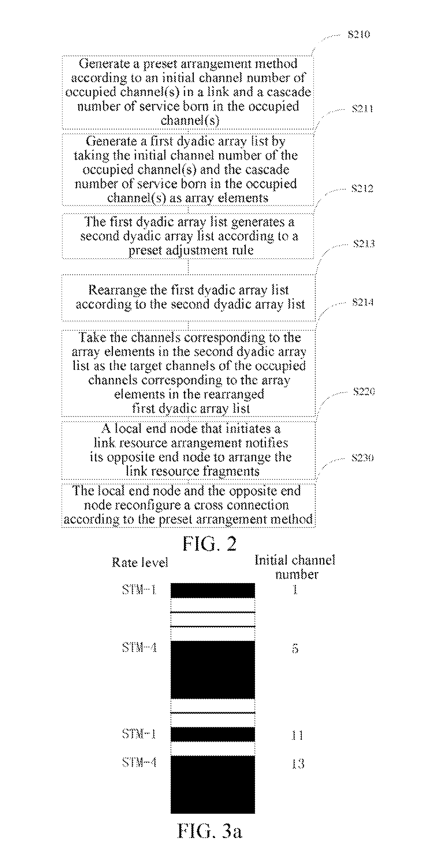
[0049]FIG. 2 is a schematic diagram of a flow chart of a method for arranging link resource fragments in accordance with the present invention, in which an initial condition is that a STM-N link has been configured and the x1, x2, . . . , xm (where 012m<N+1) channel resources in the link are already used. The steps of arranging the link resource fragments are as follows:
[0050]S210, generate a preset arrangement method according to an initial channel serial numbers of occupied channel(s) in a link and a cascade number of service born in the occupied channel(s);
[0051]S211, generate a first dyadic array list by taking the initial channel serial number of the occupied channel(s) and the cascade number of service born in the occupied channel(s) as array elements;
[0052]first, the cascade number of service born in the occupied channel(s) is checked according to the order from small channel serial number to large channel serial number, and the dyadic arrays corresponding to all the occupied...
second embodiment
[0064]FIG. 3a is a schematic diagram of an initial status of link resources of a method for arranging link resource fragments in accordance with the present invention. In a transport link of STM-16, STM-1 resource is allocated on the 1th channel, STM-4 resource is allocated on the 5th channel, STM-1 resource is allocated on the 11th channel, and STM-1 resource is allocated on the 13th channel; and the link has six channel resources left. However, due to a phenomenon of resource fragments, there is no way to allocate one more STM-4 resource, and it needs to arrange the link resource fragments.
[0065]FIG. 3b is a schematic diagram of a process of generating an ordered dyadic array list of a method for arranging resource fragments in accordance with the second embodiment of the present invention.
[0066]k=1, check the allocated 1st channel resource, the rate level is STM-1, and the dyadic array (1, 1) is generated and hung in a header of an empty link list, k=k+1;
[0067]k=2, check the allo...
third embodiment
[0079]FIG. 4a to FIG. 4e is a schematic diagram of service switching of a method for arranging link resource fragments in accordance with the present invention. The left box is the local end node and is a service signal sender, and the right box is the opposite end node and is a service signal receiver, solid lines with equal length and both sides aligned indicate each of channels in the same link, and virtual lines with arrows indicate the cross connection. The service signal switching has the following steps:[0080]1. as shown in FIG. 4a, the local end node sends a request link resource fragment arrangement message to the opposite end node, wherein, the request message comprises a link identification, all channel numbers that requires to be arranged, all arranged channel numbers and all service identifications;[0081]2. as shown in FIG. 4b, the opposite end node judges to arrange right now, sends a response message indicating that the arrangement is allowed to the local end node, an...
PUM
 Abstract
Description
Claims
Application Information
 - R&D
- Intellectual Property
- Life Sciences
- Materials
- Tech Scout
- Unparalleled Data Quality
- Higher Quality Content
- 60% Fewer Hallucinations
Browse by: Latest US Patents, China's latest patents, Technical Efficacy Thesaurus, Application Domain, Technology Topic, Popular Technical Reports.
© 2025 PatSnap. All rights reserved.Legal|Privacy policy|Modern Slavery Act Transparency Statement|Sitemap|About US| Contact US: help@patsnap.com


