Laser beam seam welding with prior laser spot welding

a laser spot welding and laser beam technology, applied in forging/pressing/hammering machines, manufacturing tools, forging/pressing/hammering apparatuses, etc., can solve the problems of gap widths that cannot be closed, coupled clamping and welding speed, and inability to close gap widths, etc., to achieve continuous laser output utilization

Active Publication Date: 2007-12-25
DAIMLER AG
View PDF20 Cites 12 Cited by
  • Summary
  • Abstract
  • Description
  • Claims
  • Application Information

AI Technical Summary

Benefits of technology

[0010]It is thus the task of the present invention to provide a process for laser beam welding, which on the one hand ensures the maintenance of a maximal gap width between the sheets and, on the other hand, makes possible a maximum utilization of the achievable welding speed.
[0013]This inventive process embodiment has the advantage that the movement of the tensioning device and the welding beam are decoupled from each other so that the former does not limit the latter. Clamping occurs only there where there is to be spot welding, and only at the time that spot welding is to take place. Thus the duration of clamping, that is, the time of application of force and the dwell time or pause time, is minimized.
[0018]In a particularly preferred embodiment of the invention the displacement (movement) of the clamping device occurs with reduced force against the sheet metal, or without pressure force. Thereby the danger of the misalignment of the sheets, already aligned relative to each other, by transmission of unintended impulses or bumps of the clamping device is minimized.
[0019]In a further advantageous embodiment of the process the spot welding occurs by forming at least one elongated welding seam, and preferably approximately 2 to 5 mm in length (depending upon the material strength, laser power, welding speed, return spring (spring back) force, etc.). Frequently, the gap width and the forces opposing the clamping when considered together are together are so large, that a certain minimum spot weld area is necessary in order to prevent a ripping apart of the spot welded seam.
[0021]Therein it is particularly preferred when the elongated rivet seam is perpendicular to the latter welding seam, since thereby the total rigidity of the joined area is maximized.
[0024]The biggest advantage is comprised therein, that the easily programmable scanner device can steer the laser beam in very short time intervals to almost any desired processing track over the surface to be processed, and thus can easily follow in particular also very precisely defined changes in the welding speed or complicated designs of lateral beam movement paths. The alternating between spot welding and welding is possible in accordance with the invention in rapid and simple manner with a laser scanner, and this makes possible an almost continuous utilization of the laser output.

Problems solved by technology

In this embodiment the clamping and welding speed are coupled and thus slow.
The latter is also limited by the requirement that the sheets, once aligned upon each other, should not be brought out of alignment by transmission of impulses.
It has been found by experience, however, that in the case of complex geometry gap-widths occur which cannot be closed without clamping techniques.

Method used


Image

  • Laser beam seam welding with prior laser spot welding
  • Laser beam seam welding with prior laser spot welding
  • Laser beam seam welding with prior laser spot welding

Examples


Embodiment Construction

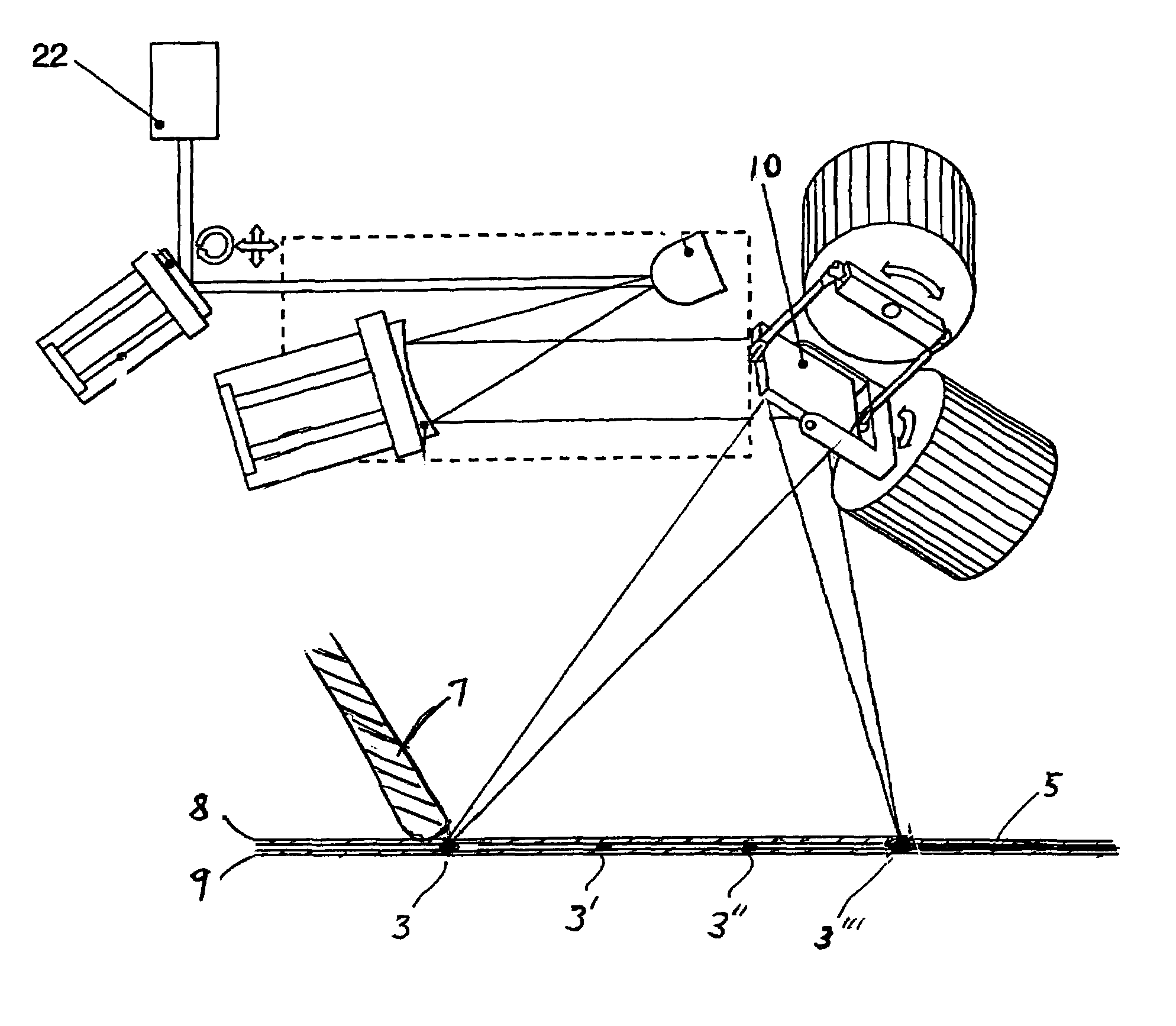
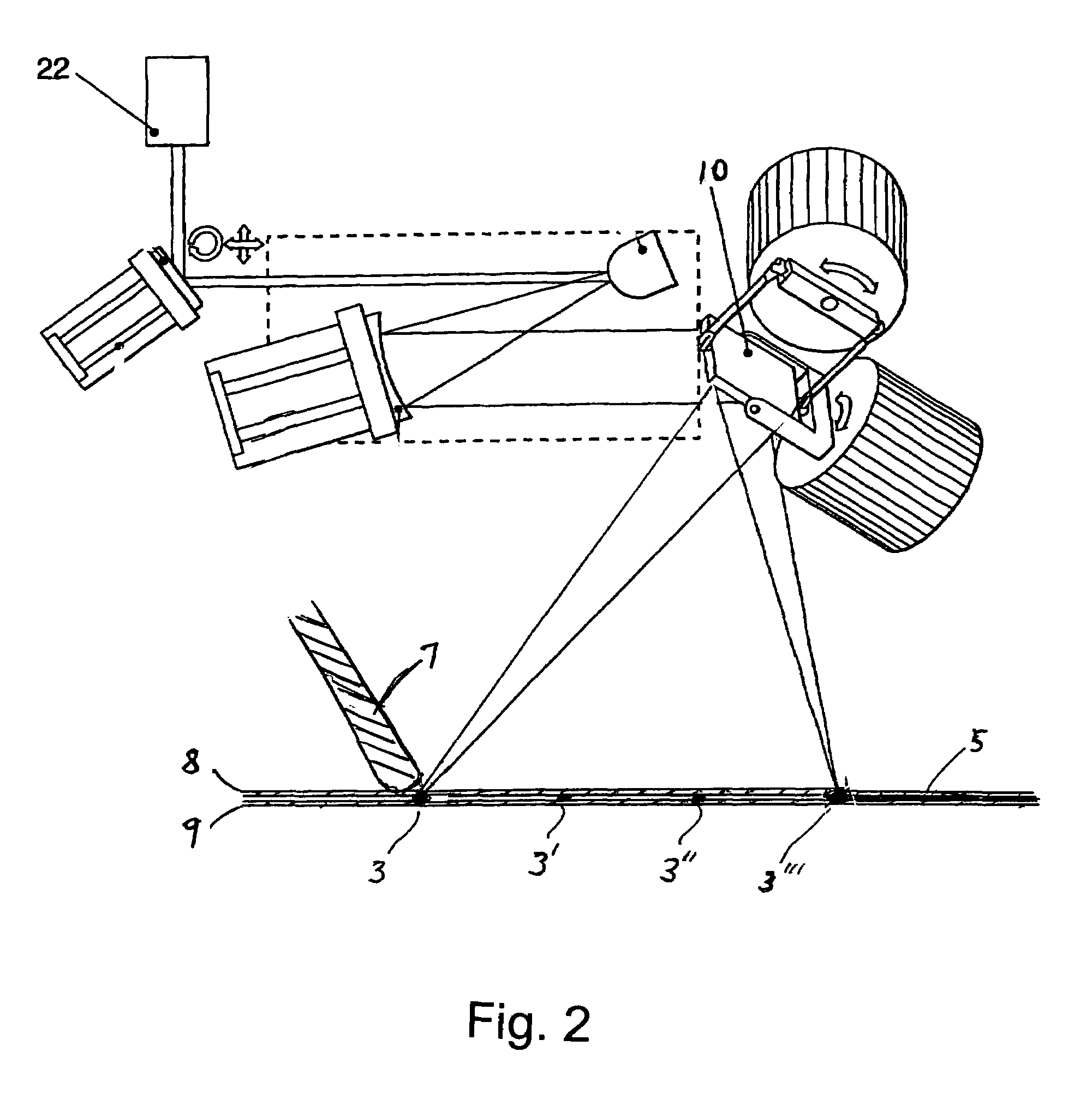
[0028]FIG. 2 shows a laser device according to DE 100 27 148, discussed above, further modified to include pressure element 7 according to the present invention. Laser 22 emits a beam which is focused in a first mirror, aimed by two axis scanning mirror 10 so as to focus at a focal point below pressure element 7 to create weld spots 3, 3′, 3″, 3′″ on one of two sheets 8, 9 such that the sheets are maintained in spaced relationship for welding. Scanning mirror is able to conduct welding to create a continuous seam 5 in the area between tack-welds 3, 3′, 3″, 3′″. In a first illustrative embodiment two steel sheets 8, 9 are oriented relative to each other and the intended welding seam is defined. A scanner device travels smoothly over it and guides a laser beam over the surface to be processed. The scanner device is comprised of a three-dimensional pivotable computer-controlled mirror system 10. The scanner device has approximately 300 mm distance to the surface of the sheet, the focus...


PUM

PropertyMeasurementUnit
lengthaaaaaaaaaa
distanceaaaaaaaaaa
widthaaaaaaaaaa

Abstract

During welding with high output power, the gaps between the pieces being joined may not exceed a maximal gap width. A process for laser beam welding is provided, which on the one hand ensures maintaining (not exceeding) a maximal gap width between the sheets and on the other hand makes possible a maximal utilization of the achievable welding speed. The sheets, prior to welding, are first spot welded, wherein they are clamped only during this spot welding in order to ensure the maintenance of a maximum gap width.

Description

BACKGROUND OF THE INVENTION[0001]1. Field of the Invention[0002]The invention concerns a process for laser beam welding with prior spot welding (tack welding, riveting). A general process of this type is already known from DE 44 14 464 C1.[0003]2. Related Art of the Invention[0004]When welding with high power density welding processes, in particular laser beam welding, electron beam welding or plasma welding, the gap between the pieces being joined may not exceed a maximum gap width, the width being determined by the particular process and material being joined. This is of particular importance in overlap-welding of body panel sheet metal in automobile construction. For this reason, the sheets of metal must generally be pressed together or clamped very near to the welding site.[0005]Generally, a stationary clamping technique, using a number of clamping elements, is employed for clamping, thereby ensuring that the permissible gap width is not exceeded at each point of the welding sea...

Claims


Application Information

Patent Timeline
Patent Type & Authority Patents(United States)
IPC IPC(8): B23K26/22B23K26/24B23K26/20B23K26/08B23K26/10B23K26/42B23K103/04
CPCB23K26/0807B23K26/10B23K26/24B23K26/421B23K26/22B23K2201/18B23K26/082B23K26/60B23K2101/18
Inventor BECKER, WOLFGANGGOTH, KLAUSPAELMER, MIKESTAHS, THOMASTODOROVIC, VLADAN
Owner DAIMLER AG
Why Eureka
Try Eureka