Method and an apparatus for calibration of an industrial robot system

a robot system and calibration method technology, applied in the direction of electric programme control, program control, instruments, etc., can solve the problems of time-consuming robot programming process, delay in production start, and inability to directly operate a robot in a real robot cell, so as to improve the calibration of an industrial robot system and high accuracy

Active Publication Date: 2013-06-04
ABB (SCHWEIZ) AG
View PDF27 Cites 22 Cited by
  • Summary
  • Abstract
  • Description
  • Claims
  • Application Information

AI Technical Summary

Benefits of technology

[0014]The object of the present invention is to improve the calibration of an industrial robot system including one or more robots and a positioner. In particular, the object is to provide a calibration with high accuracy.

Problems solved by technology

The programming of robots is a time-consuming process and the conventional methods of using the robot during the programming and the teaching process ties up the production equipment and delays production start.
However, a robot program prepared by an off-line programming system cannot directly be used for operating a robot in a real robot cell, because the positional relationship between the robot, the positioner, and the objects in the off-line environment may deviate from the actual positional relationship between the robot, the positioner, and the objects in the real robot cell.
A problem with this method is that the accuracy of the calibration depends on the skill of the robot operator to move the robot so that the calibration tip correctly points at the calibration point.
Since the radius of the rotational disc is much smaller than the distance to the other fixing point of the axis, a small error in the positions of the reference points will cause an angular error in the z-axis, which leads to a large position error of the calibration.
In a robot system including two or more robots and a positioner including one or more workstations, the calibration of the robot system becomes very complicated and time-consuming.

Method used


Image

  • Method and an apparatus for calibration of an industrial robot system
  • Method and an apparatus for calibration of an industrial robot system
  • Method and an apparatus for calibration of an industrial robot system

Examples


Embodiment Construction

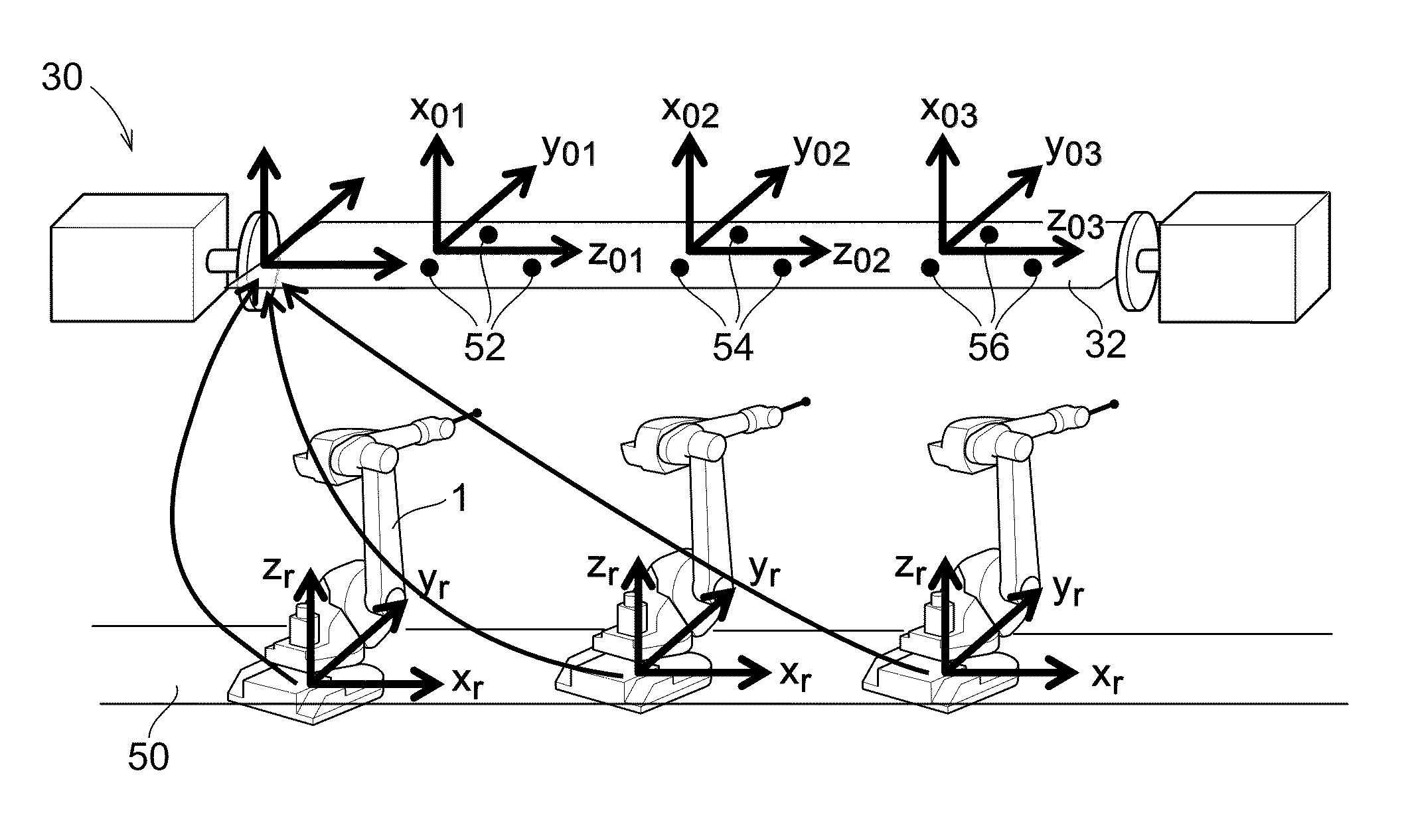
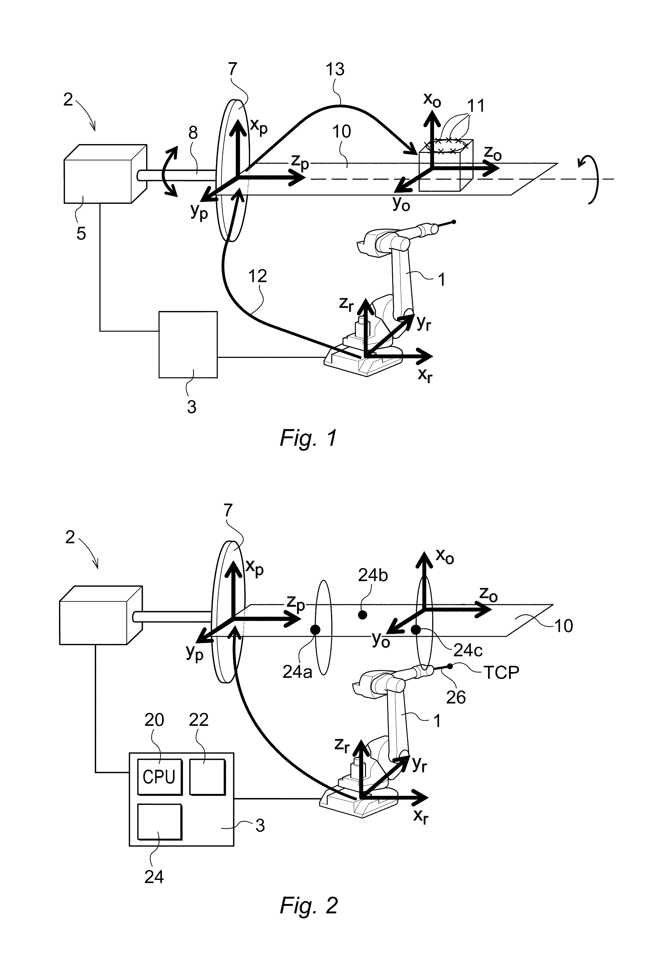
[0073]FIG. 1 shows a robot system including a robot 1 and a positioner 2. In this example, the robot 1 has three main axes and three wrist axes. A stationary foot, usually referred to as the base of the robot, supports a stand that is rotatable about a first axis. The stand supports a first arm that is rotatable about a second axis. The first arm supports a second arm which is rotatable about a third axis. The second arm supports a wrist that is rotatable about a fourth, a fifth and a sixth axis. The wrist supports a tool, in which an operating point, called TCP (Tool Centre Point), is defined. The movements of the robot 1 are controlled by a robot controller 3. The positioner 2 comprises an actuator 5 including a motor and a gear box, a rotational disc 7 connected to a rotational shaft 8 driven by the motor. The positioner 2 further comprises a fixture 10 adapted to fixedly hold a workpiece while the robot carries out work on the workpiece. The fixture 10 comprises means for attach...


PUM


Abstract

An industrial robot system has at least one robot (1) having a robot coordinate system (xr1, yr1, zr1) and a positioner (2) having a positioner coordinate system (xp, yp, zp) and adapted to hold and change orientation of a workpiece by rotating about a rotational axis. Target points for the robot are programmed with respect to an object coordinate system (xo1, yo1, zo1). A robot controller (3), at least three calibration objects (24a-c) arranged on the positioner, and a calibration tool (26) held by the robot are provided. The positions of the calibration objects are determined for at least three different angles of the rotational axis of the positioner, to determine the direction of the rotational axis of the positioner and relation between the object coordinate system and the positioner coordinate system by performing a best fit between known and determined positions of the calibration objects.

Description

BACKGROUND OF THE INVENTION[0001]1. Field of the Invention[0002]The present invention relates to a method and an apparatus for calibration of an industrial robot system comprising: at least one robot having a first robot coordinate system and configured to process a workpiece, and a positioner adapted to hold the workpiece and to change the orientation of the workpiece by rotating it about a rotational axis while the robot processes the workpiece.[0003]2. Prior Art[0004]Industrial robots are highly flexible devices used for a wide variety of operations in many different industrial applications. Robots are programmed to follow a path including a plurality of target points. The robot program includes the positions of the target points, which define the programmed path. The conventional method to program a robot is to teach the robot the path by manually moving the TCP (Tool Center Point) of the robot to the target points along the path and storing the robot positions for each target p...

Claims


Application Information

Patent Timeline
Patent Type & Authority Patents(United States)
IPC IPC(8): G06F19/00G05B19/418G05B19/04B43L13/20G01B3/00
CPCG05B19/401
Inventor ANDERSSON, BJORN E.
Owner ABB (SCHWEIZ) AG
Why Eureka
Try Eureka