Videophone over cable networks

a videophone and cable network technology, applied in the field of video telephone systems, can solve the problems of inability to implement video telephony over existing telephone lines, and inability to meet the requirements of clarity and sharpness, etc., to achieve the effect of sharing the cost of infrastructure and being efficient and inexpensiv

Inactive Publication Date: 2013-06-04
SCI ATLANTA LLC
View PDF38 Cites 9 Cited by
  • Summary
  • Abstract
  • Description
  • Claims
  • Application Information

AI Technical Summary

Benefits of technology

[0006]The present invention is directed to a videophone system and method for transporting videophone signals over an existing cable network that overcomes the disadvantages and deficiencies of known videophone systems. In particular, the present invention provides a videophone system that uses existing cable television networks to transport videophone signals to subscribers of the cable television system in an efficient and inexpensive manner. Modern digital cable television (CATV) transmission technology offers many advantages over conventional videophone and video conferencing technology. For example, much of the existing infrastructure of conventional CATV systems may be reused for videophone. Additionally, CATV provides for the carriage of existing analog television signals. Services, such as analog television, can thus share in the cost of the infrastructure and assist in providing a practical and economical means for transporting videophone traffic among consumers, i.e., subscribers of the CATV system, and between consumers and businesses.
[0007]The tree-and-branch topology of CATV distribution systems provides unique advantages for downstream (from a headend to a subscriber) broadcast or multicast. The funneling of the tree-and-branch topology in the upstream (from a subscriber to a headend or application server) direction helps to aggregate respondents in a multicast connection. CATV systems also tend to be designed with asymmetrical bandwidth. In other words, there is a very large information carrying capacity in the downstream direction, with lower, but quite adequate, capacity in the upstream direction. The downstream capacity is high enough that digital television quality video and high fidelity multichannel and / or multi language audio can be sent in the downstream direction. This combination of features is ideal for many applications, including videophone and video conferencing. For example, in distance learning, students can tune into a high quality multicast class, while the teacher can view a mosaic composite of the remotely attending students and respond to questions in nearly real time. Businesses can display and sell products and services with high quality video and audio, while seeing reduced quality video images of their customers, thereby providing more personalized, albeit remote, service. Tolls may be paid by the businesses, such as, for example, advertising and sales applications, or even by consumers for services analogous to those that now charge by means of 900 numbers, for example.
[0008]The CATV system provides connection to consumers and businesses alike. Existing long distance high-speed networks, including telephone and high-speed satellite television networks, can provide transport of videophone signals between different CATV systems, thereby providing a link between users of different systems. These same long distance networks can provide videophone connects to remote servers as well. Because of the numerous advantages associated with CATV systems, the preferred embodiment of the instant invention described herein uses CATV to transport the videophone signals. However, it will be understood that the invention described herein is not limited to CATV systems. For example, Asynchronous Transfer Mode (ATM) networks may also be used.
[0013]Having the VP as part of the STT provides significant operational and cost advantages. For example, the VP card would use the memory and processor capacity of the STT, thereby sharing resources, and proving efficiency and lowering costs. For example, in the stand-alone VP embodiment described earlier, the VP must derive its own NTSC signal and therefore must have the ability to capture the signal. On the other hand, the SIT must, by definition, include data capture capability. Therefore, in the case where the VP is integrated with the STT, the VP would not have to have display capability because it is shared with the STT. As an alternative to STTs, cable modems may be used to link the VP with a given network or display device. Moreover, an STT may be configured to evaluate, or act as, a cable modem for transmission and reception of videophone signals where the VP provides its own display capabilities.
[0014]Accordingly, it is an object of the present invention to provide an efficient and cost effective videophone transport system that overcomes the disadvantages of the prior art and provides high-quality visual video signals from proved videophone functionality.
[0017]It is still another object of the present invention to provide signal conversion capability to allow numerous videophone signaling specifications to exist on a given system or between different CATV systems.

Problems solved by technology

However, many disadvantages are present when implementing video telephony over existing telephone lines.
Chief among the problems is that of unacceptable image quality.
The images do not have the requisite clarity and sharpness to which consumers have become accustomed.
Additionally, motion of the video frames is frequently jittery and synchronism between the motion of the video and the corresponding audio is lost.
However, few consumers have access to such networks except via modems that are too slow to accommodate videophone signals in an acceptable manner, i.e., without delays and jitter, thereby failing to alleviate the problems with conventional videophone over existing telephone networks.
Many of the above methods for providing videophone services to consumers and businesses suffers from the disadvantage that a new infrastructure must be built at great, almost prohibitive, cost.
Furthermore, none of the above-mentioned alternatives has the ability to carry existing analog television signals.

Method used


Image

  • Videophone over cable networks
  • Videophone over cable networks
  • Videophone over cable networks

Examples


Embodiment Construction

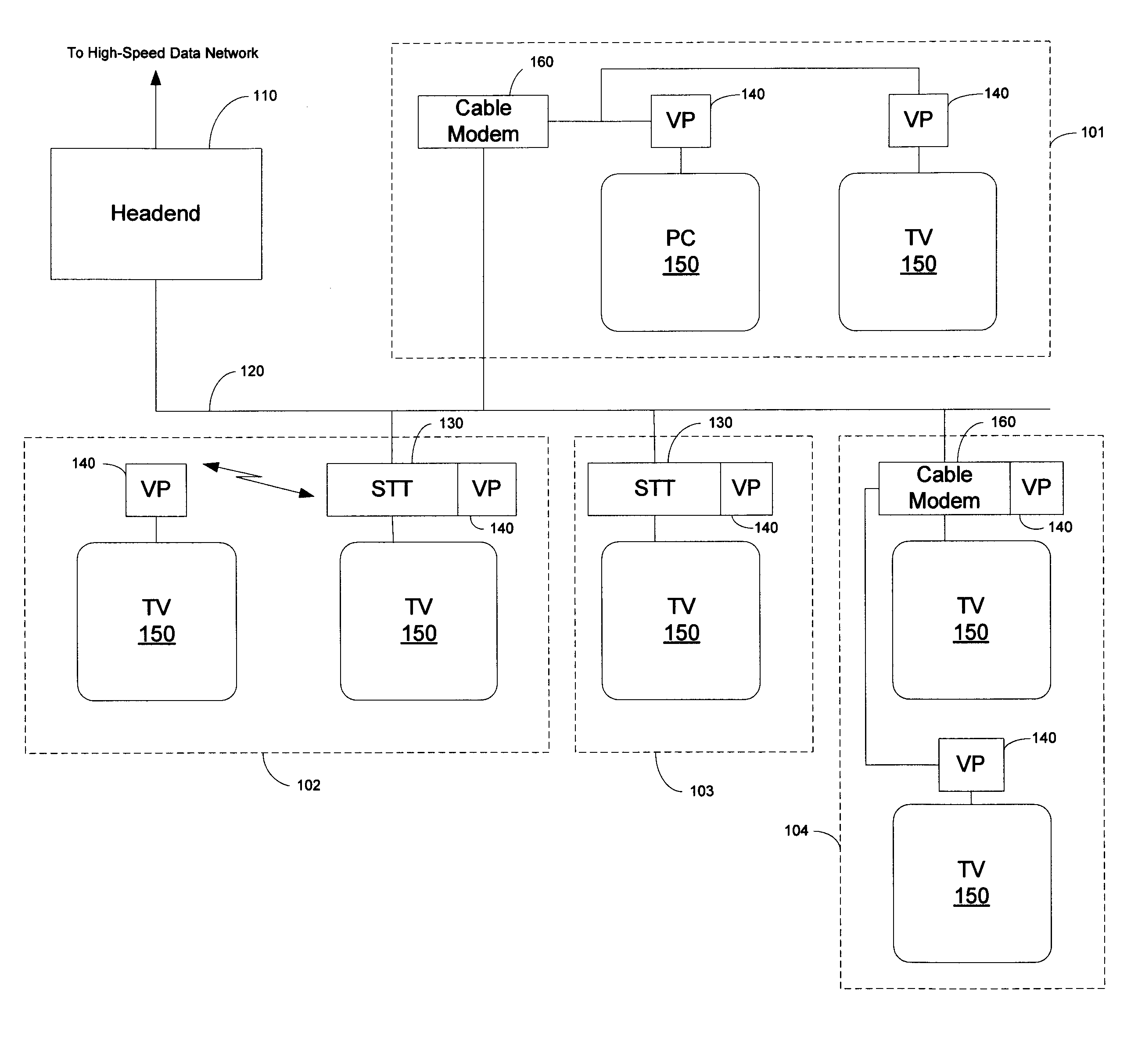
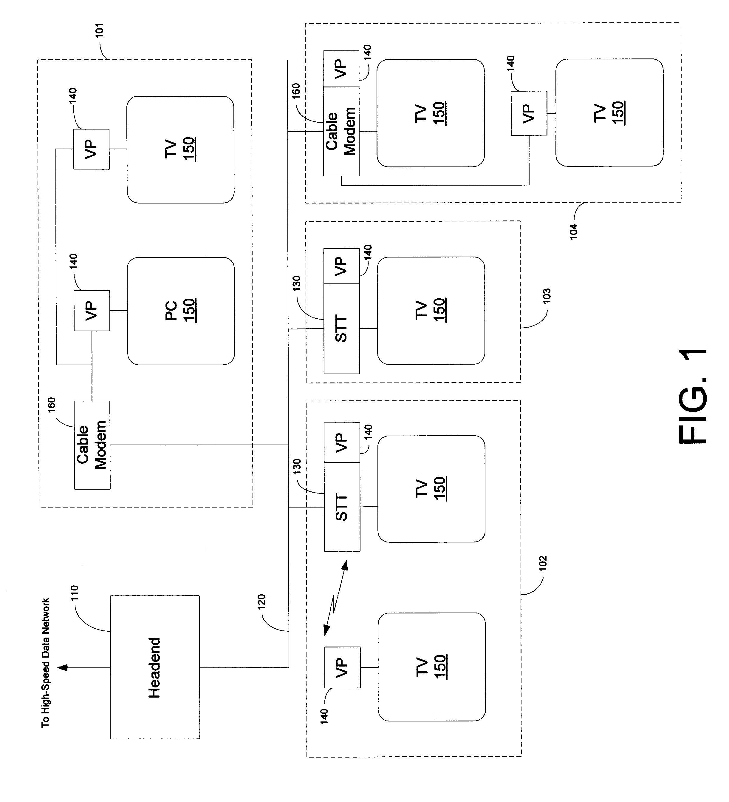
[0030]Referring now to FIG. 1, a general block diagram of a CATV system 100 having several uses 101, 102, 103, 104 equipped with videophone capabilities is shown. The headend 110 is connected to the users 101, 102, 103, 104 via a cable 120, which may include various media, such as, for example, fiber optic, copper, or hybrid-fiber-coax (HFC). The headend 110 may also be connected to another CATV network 100′ via a high-speed transmission medium 38, such as, for example a satellite network, a high-speed telephone network, or the like. Various videophone configurations are shown in FIG. 1. In a standard videophone configuration, such as that of user 103, data is received by an STT 130 and communicated to a VP 140 co-located with the STT 130. The VP 140 processes the data and provides it either directly to a display device 150, such as, for example, a television set, or provides it to STT 130 for further processing and display by the display device 150. In an alternative configuration ...


PUM


Abstract

The present invention is directed to a videophone system implemented over a cable television network. The instant invention provides a videophone comprising a camera for capturing images associated with a videophone signal, a videophone unit and a set top terminal or cable modem connecting the videophone to a cable television network. Videophone signals created at the call origination site are encoded and transported to a predetermined destination over an existing cable television network. The system uses IP addresses as phone number on the network. Additionally, transport of videophone signals between different cable systems is accomplished via a high-speed long distance data network, such as, for example, a satellite network, that provides communication between the headends of the different cable television systems. The set top terminal may be a conventional subscriber terminal, a cable modem or a subscriber terminal configured to operate as a cable modem. The set top terminal provides the interface between the videophone and the cable television system. More than one videophone may be connected to a single set top terminal. Display of videophone data may be achieved using any conventional display device, including a television set or a personal computer monitor. Accordingly, the videophone system described herein takes advantage of increased bandwidth and lower cost realized by using existing cable television infrastructure and technology.

Description

RELATED INFORMATION[0001]The present application is a continuation of U.S. patent application Ser. No. 09 / 481,155, Rodriguez et al., entitled “Videophone over Cable Networks,” filed Jan. 12, 2000 now abandoned, which is a continuation of U.S. patent application Ser. No. 08 / 857,595, Rodriguez et al., filed May 16, 1997 now abandoned.FIELD OF THE INVENTION[0002]The present invention relates generally to a video telephone system. In particular, the instant invention is directed to a video telephone system implemented over a cable network, such as, for example, an existing cable television (CATV) network.BACKGROUND OF THE INVENTION[0003]Recent advances in telephony have made possible full duplex audio communication in conjunction with full duplex video communication. However, many disadvantages are present when implementing video telephony over existing telephone lines. Chief among the problems is that of unacceptable image quality. The images do not have the requisite clarity and sharp...

Claims


Application Information

Patent Timeline
Patent Type & Authority Patents(United States)
IPC IPC(8): H04N7/173
CPCH04N7/147H04N7/148H04N7/15H04N21/236H04N21/4223H04N21/42676H04N21/4316H04N21/4788H04N21/6118H04N21/64322
Inventor RODRIGUEZ, ARTURO A.SIMERLY, TIMOTHY W.ROVIRA, LUIS A.WALL, JR., WILLIAM E.PATEL, NEILESH R.
Owner SCI ATLANTA LLC
Why Eureka
Try Eureka