

Roller type transmission device
a transmission device and roller technology, applied in the direction of yielding couplings, toothed gearings, gearing, etc., can solve the problems of difficult to reduce the size of the adjustment plate, and the inner gear ring in a diametrical, and achieve the effect of advantageous cost and structural simplicity
- Summary
- Abstract
- Description
- Claims
- Application Information
AI Technical Summary
Benefits of technology
Problems solved by technology
Method used
Image

Examples
first embodiment
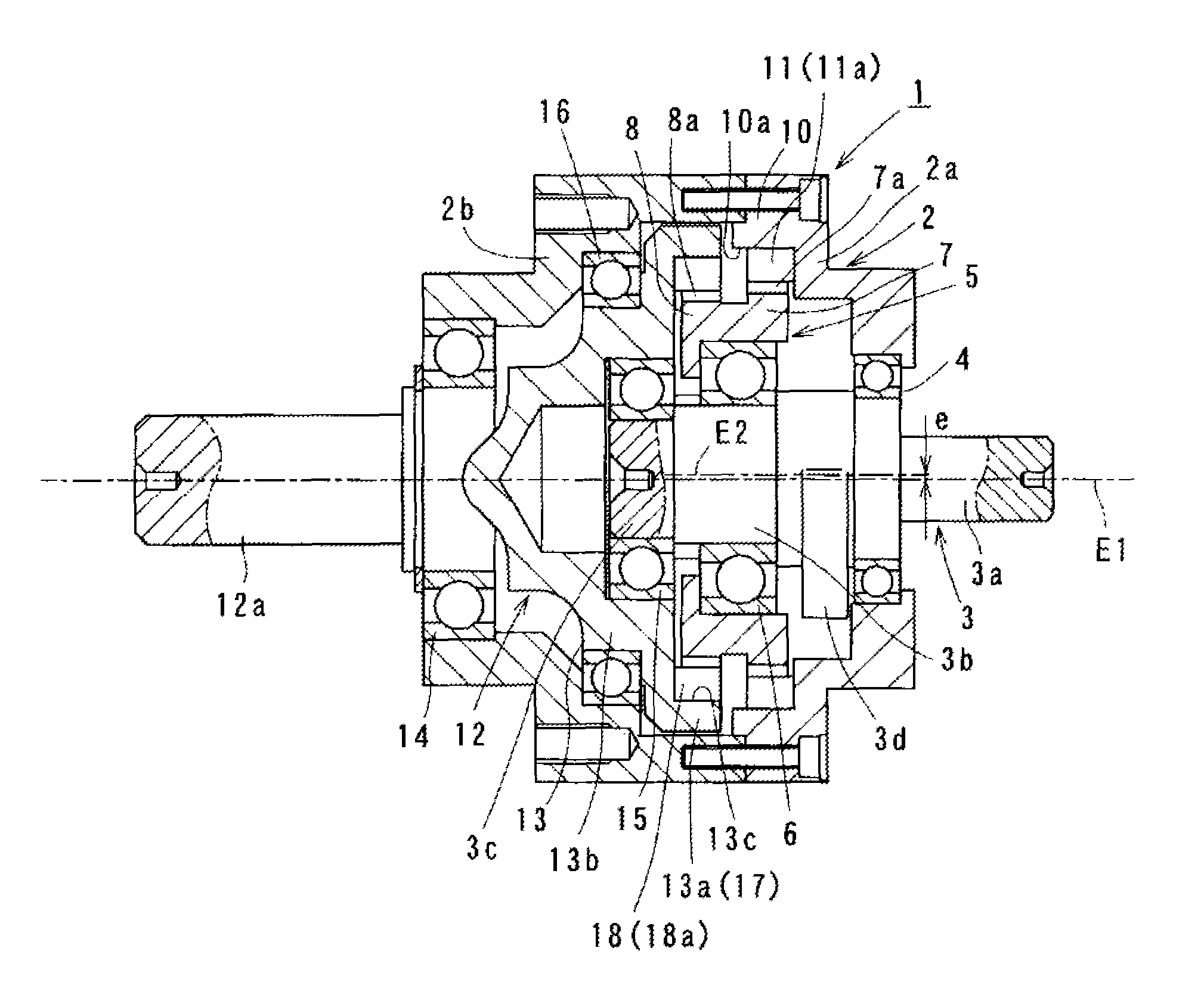
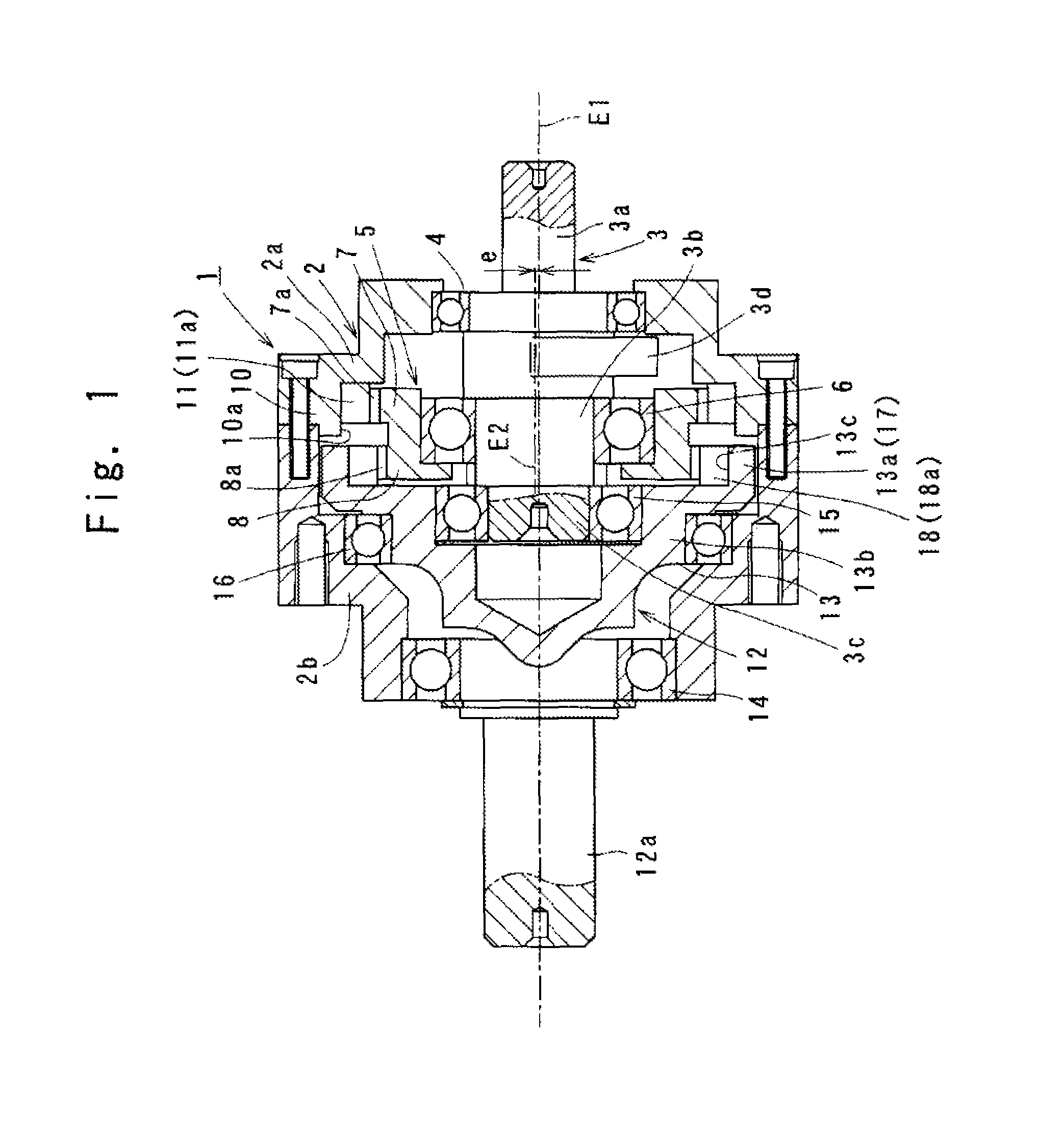
[0059]Referring to FIGS. 1 through 6 which show a roller type transmission device 1 and its related structures according to the invention. As shown in FIG. 1, a cylindrical housing 2 has a first housing portion 2a and a second housing portion 2b which are concentrically connected together in abutting relationship with each other. A rotational shaft 3 is concentrically provided within the housing 2 in an axial direction.
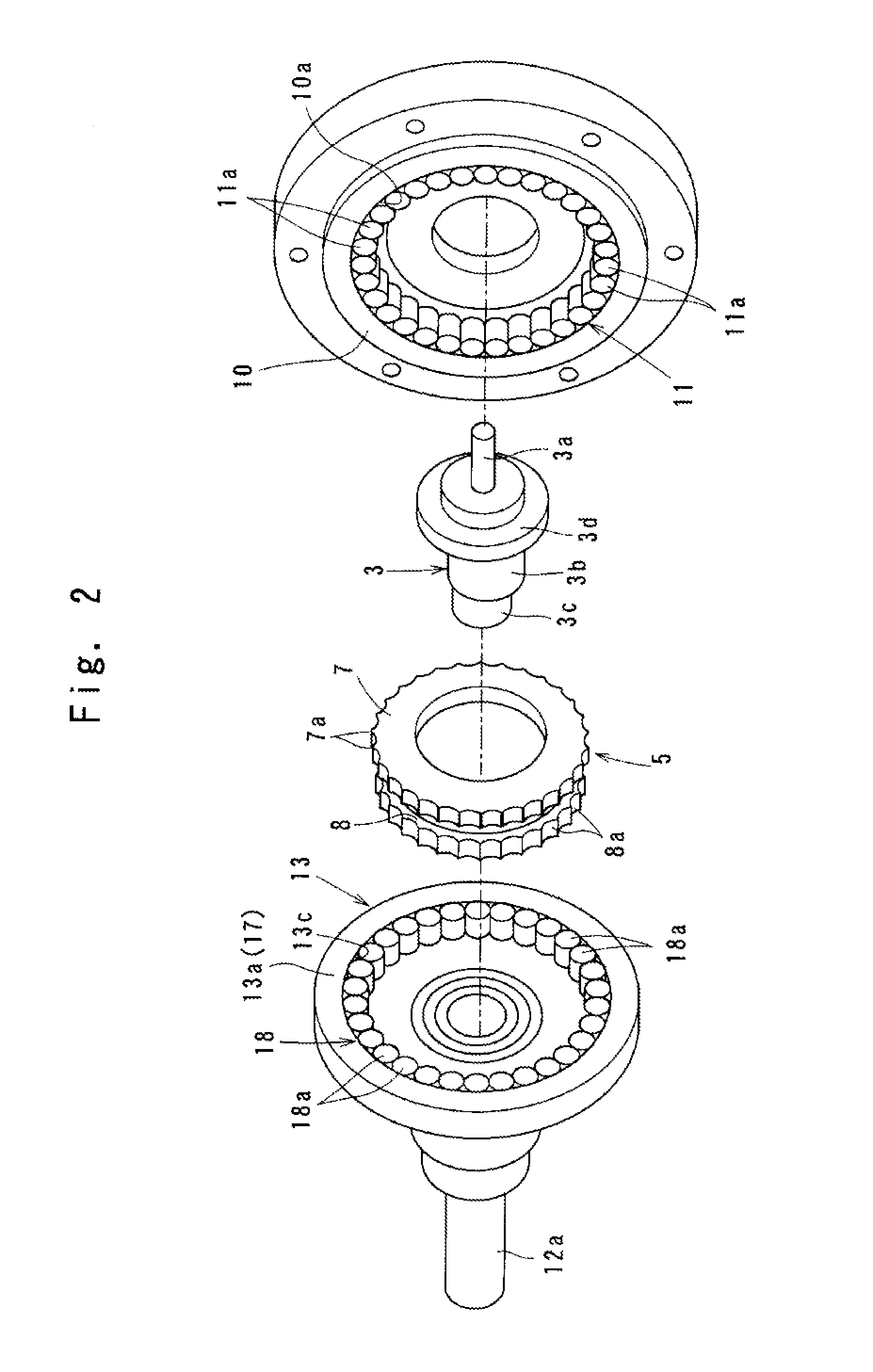
[0060]The shaft 3 is rotatably supported at an open-ended portion of the first housing portion 2 by means of a ball bearing 4. One end of the shaft 3 has a diameter-reduced input shaft portion 3a, a middle section of the shaft 3 forms an eccentric shaft portion 3b, and the other end of the shaft 3 defines a diameter-increased support portion 3c. Between the input shaft portion 3a and the eccentric shaft portion 3b, the shaft 3 has a weight portion 3d integrally provided as a balancer in abutting relationship with the ball bearing 4.
[0061]The eccentric shaft portion 3b...
second embodiment
[0102]FIGS. 7, 8 show the invention in which a metal retainer 19 is provided in the form of a thin and annular plate configuration. As shown in FIG. 7, the retainer 19 has a width (H) identical to the diameter (d) of the pin rollers 18a, while at the same time, having an outer diameter (D1) dimensionally corresponding to an inner diameter (D2) of the controllable ring 17.
[0103]As shown in FIG. 8, the retainer 19 is concentrically located on one end side of the array 18 of controllable pin rollers so as to be fixed to each center (Gp) of the pin rollers 18a by means of welding procedure (e.g., resistance welding, TIG welding, plasma welding or laser welding procedure).
[0104]With the retainer 19 fixed as above, it becomes possible to firmly maintain the array 18 of controllable pin rollers in the circular fashion.
[0105]Instead of the welding procedure, a machine screw may be used to fix the metal retainer 19 to the array 18 of the pin rollers. The width (H) of the retainer 19 is not n...
third embodiment
[0106]FIG. 9 shows the invention in which the controllable ring 20 is provided on the other periphery side of the transmission ring body 5 in lieu of the controllable ring gear 8, and the controllable ring gear 21 is provided on the diameter-increased ring portion 13a of the rotational ring 13 in lieu of the array 18 of controllable pin rollers. Namely, an array 22 of controllable pin rollers 22a is press fit into a controllable ring 20, and teeth 21a of a controllable ring gear 21 are circumferentially defined continuously on an outer surface of the diameter-increased ring portion 13a. This makes some of the controllable pin rollers 22a always engage with the respective teeth 21a of the controllable ring gear 21.
[0107]In the roller type transmission device in which the controllable ring 20 is placed in lieu of the controllable ring gear 8, and the controllable ring gear 21 is placed in lieu of the array 18 of controllable pin rollers, the same advantages as obtained in the first em...
PUM
 Abstract
Description
Claims
Application Information