
Filter cartridge having central plenum and housing sidewall

a filter cartridge and housing technology, applied in the direction of filtration separation, separation process, breathing protection, etc., can solve the problems of limiting the service life of the filter cartridge, not having a housing sidewall that defines the cartridge perimeter, and not providing a dual flow pattern for the filter cartridge, so as to reduce the pressure drop, and increase the exposed surface area

Active Publication Date: 2013-06-11
3M INNOVATIVE PROPERTIES CO
View PDF36 Cites 32 Cited by
  • Summary
  • Abstract
  • Description
  • Claims
  • Application Information

AI Technical Summary

Benefits of technology

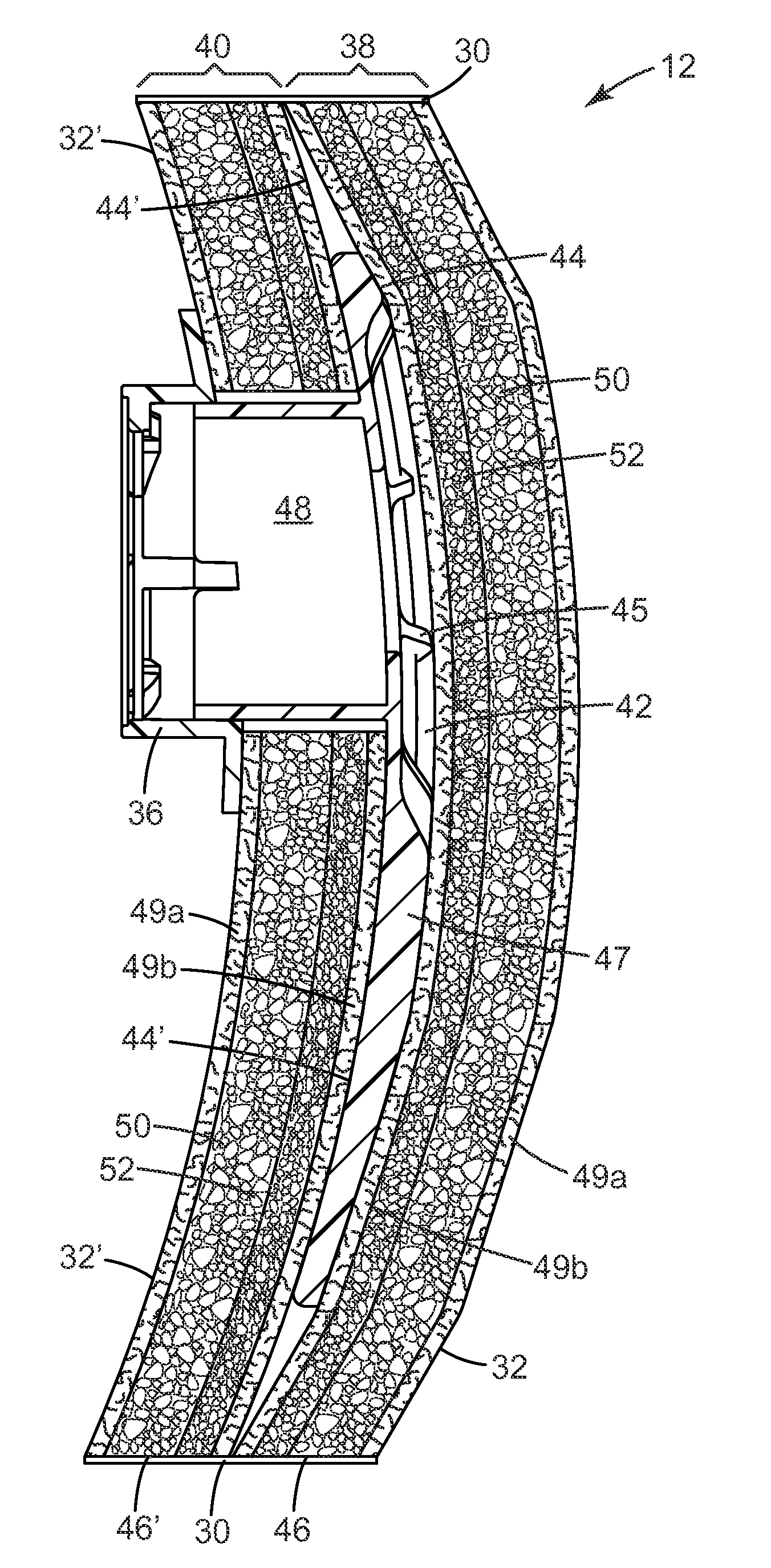
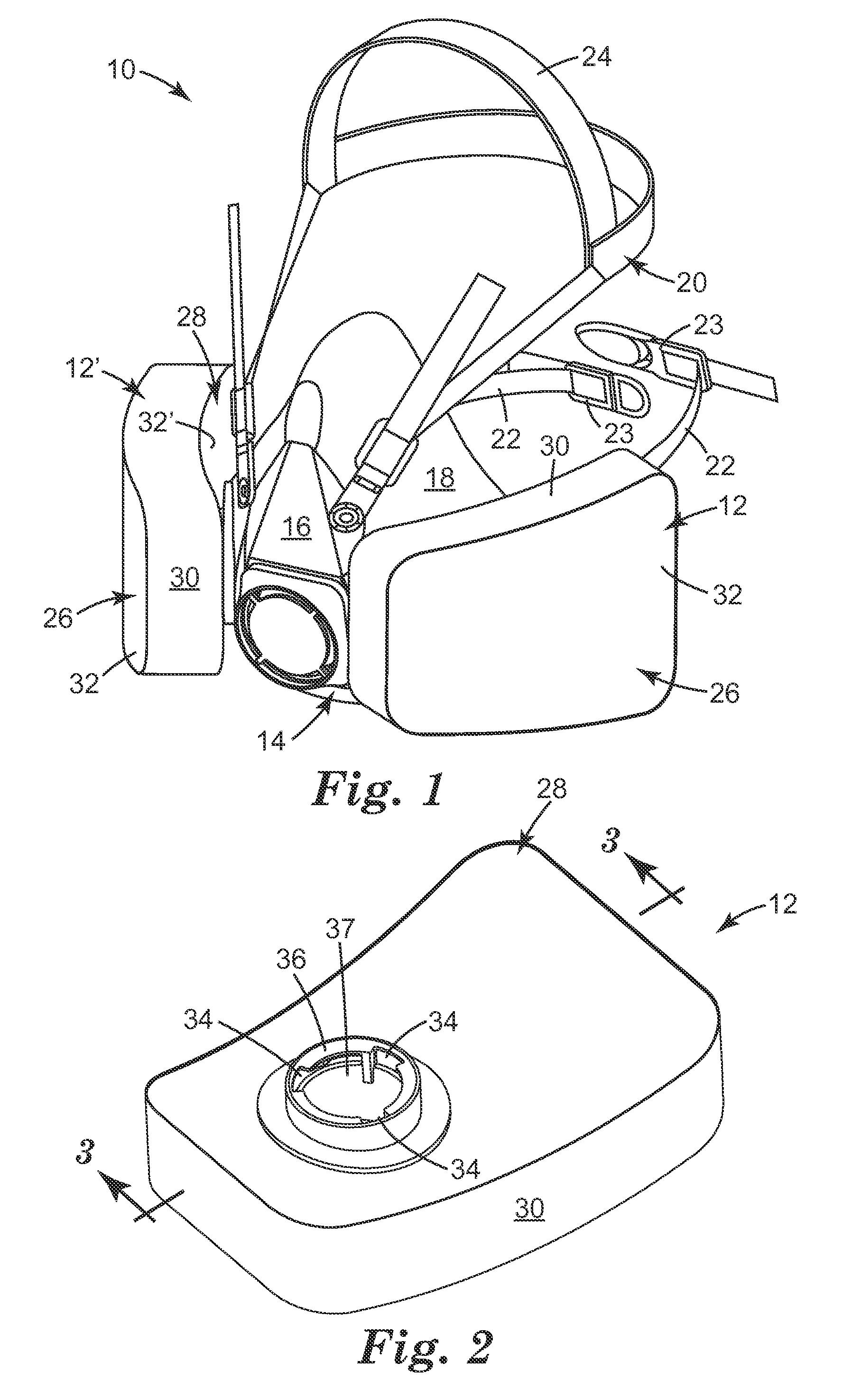
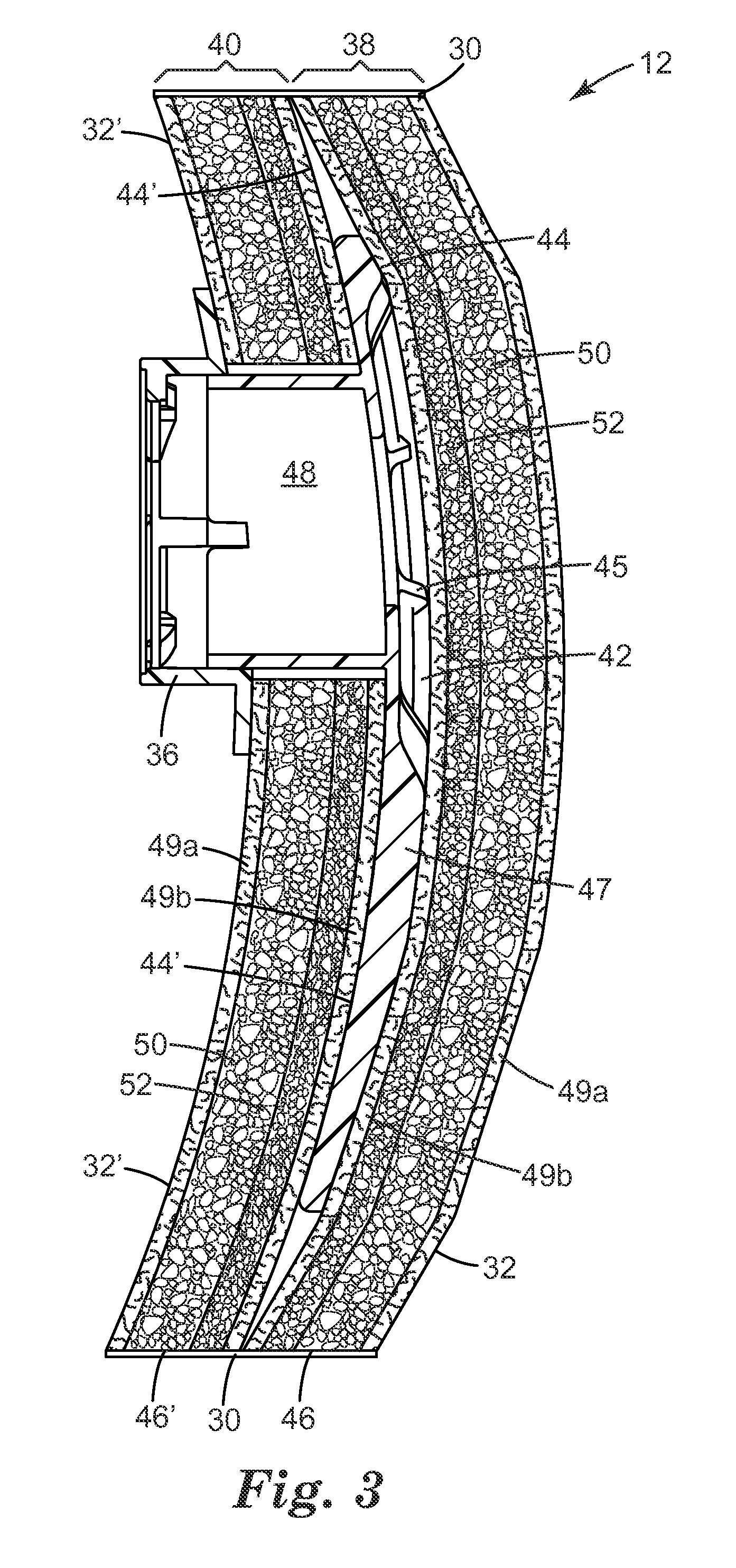
The present invention provides a filter cartridge that provides extensive surface area for filtration by having two layers of filter media separated by a central plenum. This allows for lower pressure drops across the filter medium, improving user comfort. The housing sidewall provides additional depth and thickness to the filter cartridge, increasing its volume and lifespan. The individual components of the filter cartridge, which are lightweight and have little structural capacity, come together to form a three-dimensional, lightweight construction that can function as a filter cartridge. The method of assembly is quick, easy, and can lower manufacturing costs. Overall, the filter cartridge of the present invention provides longer service lives and improved comfort for respirator users.

Problems solved by technology

The typical filter cartridge also has not provided a dual flow pattern to reduce pressure drop across the filter media.
Although bifurcated or dual flow cartridges also have been developed, which contain two spaced layers of filter media separated by a central plenum—see U.S. Pat. Re 35,062 to Brostrom et al.—these dual flow products, however, have not had a housing sidewall that defines the cartridge perimeter.
As a result, the dual flow cartridges have generally contained lower volumes of filter media, which has placed limits on filter cartridge service life.

Method used


Image

  • Filter cartridge having central plenum and housing sidewall
  • Filter cartridge having central plenum and housing sidewall
  • Filter cartridge having central plenum and housing sidewall

Examples


example 1

[0051]Carbon loaded BMF webs were made according to U.S. Patent Application No. 2006 / 096911. The polymer fibers were produced using Vistamaxx™ 2125 resin, produced my ExxonMobil.

[0052]The bulk carbon loaded webs were compressed to about 4.7 mm in thickness using a Carver heated platen press that had 12 inch by 12 inch platens. The platen temperatures were 200° F. The pressure was 3000 pounds per square inch (psi) total, and the press time was 5 seconds.

[0053]In the following description, OV refers to organic vapor, and gsm means grams per square meter. The bulk and polishing layers had the construction set forth in Table 1.

[0054]

TABLE 1Properties and MaterialsOV BulkOV PolishingWeb weight total(gsm)1482428Polymer wt (gsm)5442CarbonKuraray GCKuraray GC12 × 2060 × 150Web Thickness - final4.5 mm2 mm

[0055]The filter was assembled having the following order of layers:[0056]OV Bulk[0057]OV Bulk[0058]OV Polishing[0059]Plenum structure[0060]OV Polishing[0061]OV Bulk[0062]OV Bulk

[0063]The la...


PUM

PropertyMeasurementUnit
thicknessaaaaaaaaaa
widthaaaaaaaaaa
widthaaaaaaaaaa

Abstract

A filter cartridge 12 that has a first and second layer of filter media 38, 40 that each have first and second major surfaces 32, 44 and a perimeter 46 and that each contain active particulate that is bonded together. A plenum 42 is disposed between the first and second layers of filter media 38, 40 such that the plenum 42 interfaces with the second major surface 44, 44′ of each layer of filter media. A housing sidewall 30 extends from the first layer of filter media 38 to the second layer of filter media 40 and is secured to the perimeter 46 of the first and second layers of filter media. The first major surfaces 32, 32′ of the first and second layers of filter media 38, 40 are each fluid permeable and are each in fluid communication with an exterior gas space. A filter cartridge 12 having such a construction provides a bifurcated flow pattern in a higher volume structure.

Description

[0001]The present invention pertains to a filter cartridge that has a central plenum in conjunction with a housing sidewall. The housing sidewall frames the cartridge and may be made from a roll based material that is adhered to the perimeter of filter media layers, which layers are disposed on opposing sides of the central plenum. The filter cartridge is suitable for use in a respirator that provides clean filtered air to the wearer.BACKGROUND[0002]Respirators are devices that protect workers and others from harmful health effects associated with airborne hazards. The devices are worn about the face, acting to remove unwanted contaminants from the breathing air supply. The contaminants may be solid particles such as fumes, bioaerosols, or other particles, or they may be gasses or vapors, or combinations of such substances.[0003]Respirators come in a variety of shapes and forms and are commonly designed according to the wearer's protection needs. Respiratory products range from simp...

Claims


Application Information

Patent Timeline
Patent Type & Authority Patents(United States)
IPC IPC(8): B01D46/00A62B23/02
CPCA62B7/10A62B19/00A62B23/02B01D39/163B01D39/2062B01D2239/065B01D2239/086B01D2239/10A62B18/02A62B23/00B01D39/00
Inventor LEGARE, PIERREBILLINGSLEY, BRITTON G.
Owner 3M INNOVATIVE PROPERTIES CO
Learn More