
System and method for a self-referencing interferometer

Active Publication Date: 2013-06-11
LEIDOS
View PDF3 Cites 14 Cited by
  • Summary
  • Abstract
  • Description
  • Claims
  • Application Information

AI Technical Summary

Benefits of technology

The present invention provides improvements to interferometers by reducing their size and complexity. Two embodiments are discussed: an improved spatial phase shifting assembly and a self-referencing interferometer. These improvements allow for better identification and correction of aberrations in signal beams, resulting in improved beam quality.

Problems solved by technology

The limitations with prior art interferometers are that they can be large in size and can weigh several pounds or more, limiting their implementation.
There are a number of technical limitations with prior art interferometers as well.
When a signal beam and a reference beam do not travel the same path within the interferometer, the two beams may be subject to aberrations that are not common to the paths of each beam.
Since the interferometer measures the phase differences between the two beams, non-common path aberrations distort the desired measurement.
Designing an interferometer to correct for these aberrations adds to the complexity of the interferometer.
The numerous optical surfaces limit the optical throughput of the spatial phase shifting assembly and worsen the problem of non-common path aberrations.
Furthermore, having numerous custom optical elements and a custom mounting assembly in a conventional spatial phase shifting assembly greatly increases the cost of the assembly.
The weight and size of conventional spatial phase shifting assemblies also limits prior art interferometers.
Accordingly, the weight and size of conventional spatial phase shifting assemblies limits how interferometers can be implemented and in which applications they can be used.
Another limitation in conventional interferometers is the length of the single mode fiber through which the reference beam passes.
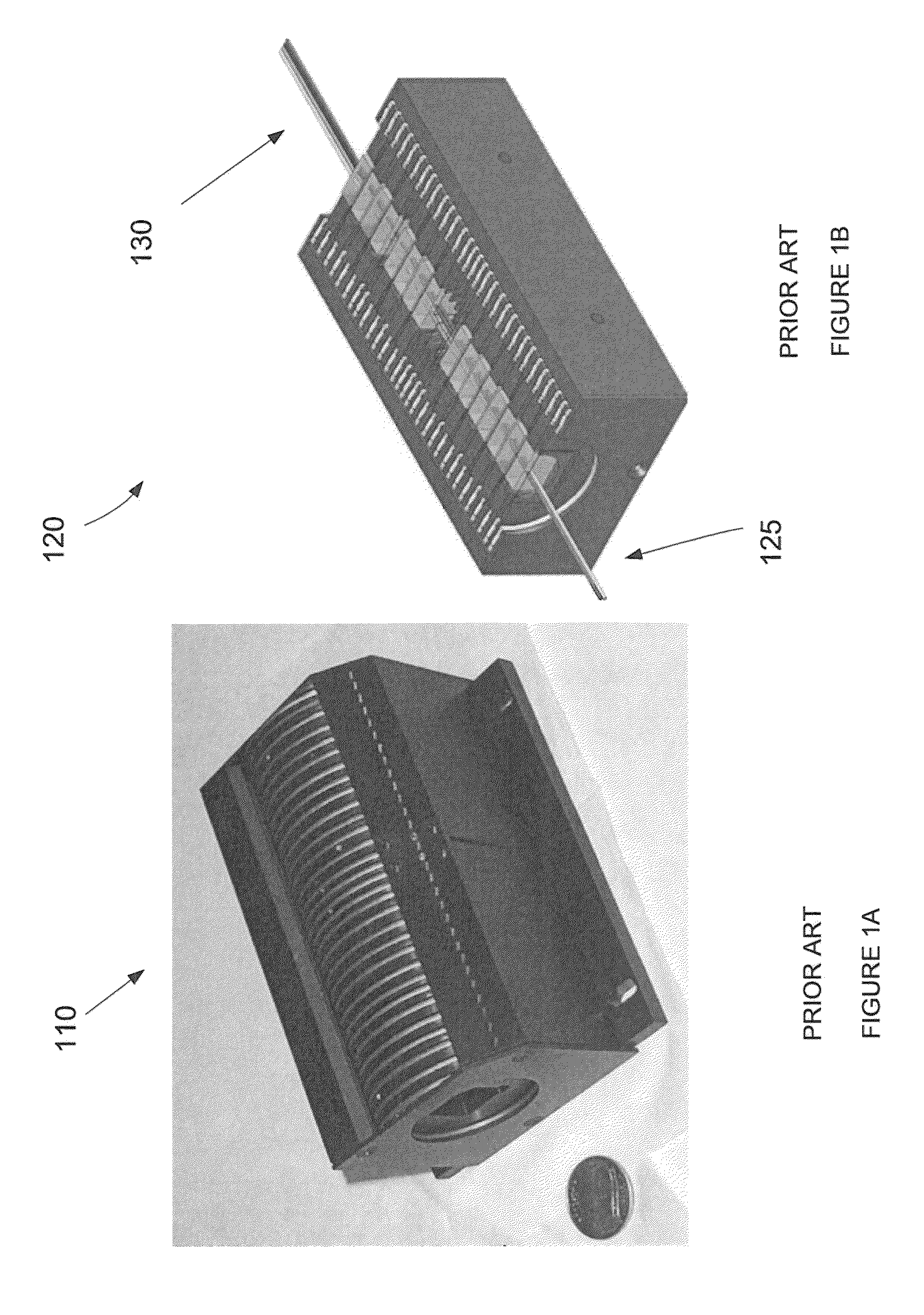
Finally, the polarization requirements of a conventional interferometer using a spatial phase shifting assembly such as the one illustrated in FIGS. 1A and 1B further limit implementation of conventional interferometers for directed energy and laser communications applications.
Furthermore, the length of the reference fiber creates a greater probability that mechanical and thermal disturbances can alter the polarization of the reference beam and reduce the measurement accuracy of the interferometer.

Method used


Image

  • System and method for a self-referencing interferometer
  • System and method for a self-referencing interferometer
  • System and method for a self-referencing interferometer

Examples


Embodiment Construction

[0025]The invention is directed to components and methods for improved interferometers. Although the exemplary embodiments of the improved interferometers will be described in the following text and the associated figures, those skilled in the art will recognize that the exemplary embodiments can be modified in various ways within the scope of the invention. For example, the exemplary embodiments described herein include certain conventional components such as lenses and mirrors. Those of skill in the art will recognize that various different types of lenses and mirrors can be substituted for the conventional components described herein. Those of skill in the art also will recognize that the configuration of the conventional lenses and mirrors described herein can be modified within the scope of the invention.

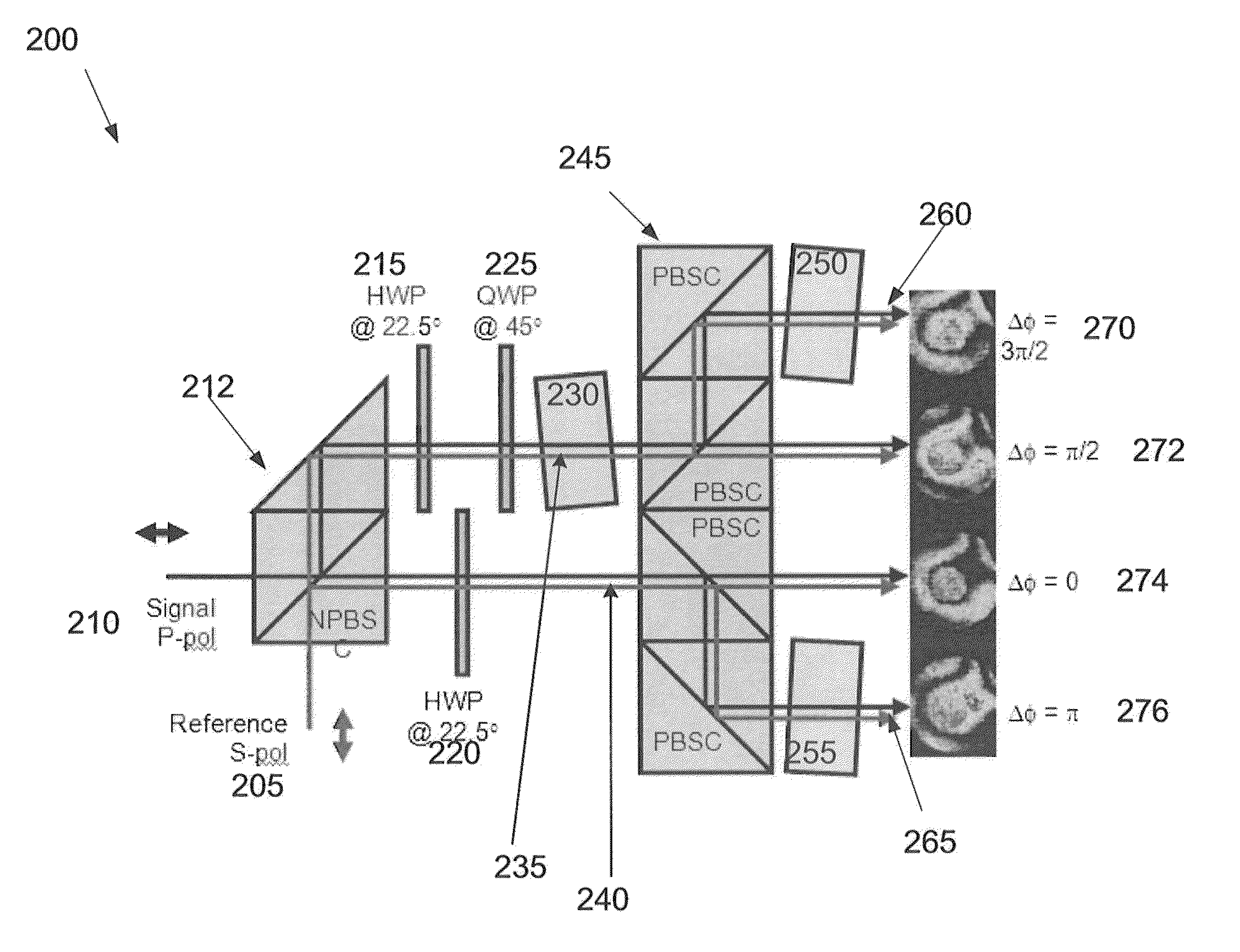
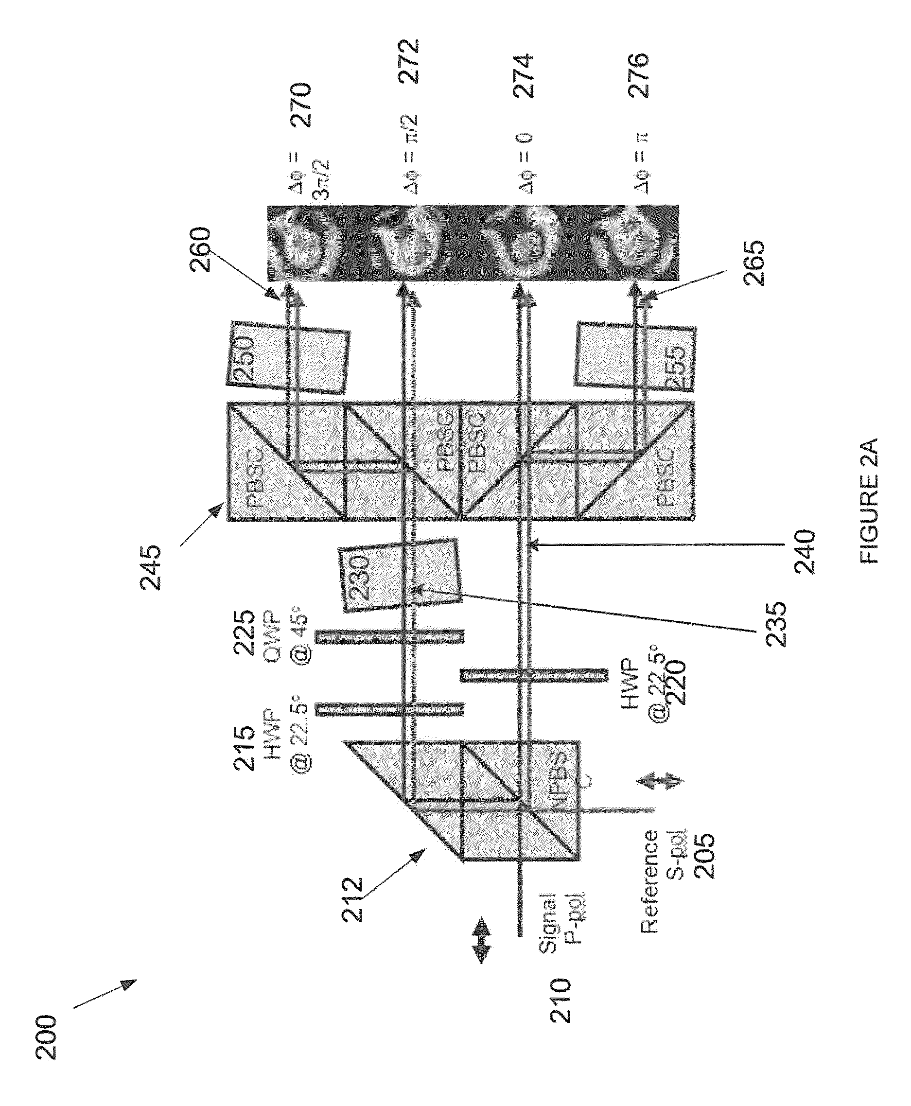
[0026]Turning to FIG. 2A, an exemplary embodiment of a miniature spatial phase shifter 200 is illustrated. The miniature spatial phase shifter 200 improves upon several of the ...


PUM


Abstract

Systems and methods are described herein for a self-referencing interferometer. The interferometer can comprise an improved spatial phase shifter that reduces the number of components, size and complexity of the spatial phase shifter and maintains a common path for a combined reference beam and signal beam. The self-referencing interferometer further comprises a single mode fiber shunt for filtering the reference beam and further reducing the size of the interferometer. The angle of the reference beam can be tilted before being recombined with the single beam which further simplifies the spatial phase shifting component of the interferometer.

Description

BACKGROUND OF THE INVENTION[0001]1. Field of the Invention[0002]The present invention relates generally to the field of interferometers and more particularly to a self-referencing interferometer that uses spatial phase shifting to reconstruct optical wave fronts.[0003]2. Description of the Related Art[0004]Phase shifting interferometers used in directed energy or laser communications applications typically consist of a light source that is split into two beams—a reference beam and a signal beam. The two light beams travel different paths, the reference beam is spatially filtered, and then the beams are recombined in such a way that the wave front of the signal beam can be determined. Phase shifting interferometry can be used to accurately determine the phase differences between the two beams. By spatially filtering the reference beam to create a clean spherical wave front, the shape of the wave front of the signal beam can be determined. The recombined beams produce an optical inter...

Claims


Application Information

Patent Timeline
IPC IPC(8): G01B9/02
CPCG01B9/02097G01B9/02081G01B2290/70
Inventor RHOADARMER, TROYBERG, ERIC
Owner LEIDOS
Learn More