Liquid crystal waveguide having two or more control voltages for controlling polarized light

a liquid crystal waveguide and control voltage technology, applied in non-linear optics, instruments, optics, etc., can solve the problems of difficult to compact such mechanical devices, undesirable mechanical control of light, and limited lifetime of mechanically moving devices

Active Publication Date: 2013-06-11
ANALOG DEVICES INC
View PDF78 Cites 39 Cited by
  • Summary
  • Abstract
  • Description
  • Claims
  • Application Information

AI Technical Summary

Problems solved by technology

However, mechanical control over light is undesirable for several reasons.
First, it is difficult to make such mechanical devices compact.
Second, the mechanical nature of such moving devices have limited lifetimes due to mechanical wear and failure issues.
Third, mechanical devices are inherently vibration sensitive, which limits the type of environment in which they can be used.
Finally, mechanical devices necessitate a level of design complexity including gears, bearings, and other mechanical components, which add cost, expense, and maintenance issues to such designs.
These devices can be power consumptive, which may be prohibitive for many applications.
With conventional waveguides, electro-optic materials, such as LiNbO3, are employed whereby a voltage applied across such material changes the index of refraction, n. However, with these conventional techniques, the index of refraction can only be changed a very small amount, such as 0.0001 per kilo volt for bulk materials such as LiNbO3.
This limitation makes this type of light control extremely limited due to the high amount of voltage needed for significant light control.
Use of conventional liquid crystal optical techniques to achieve active optical control would generally require prohibitively thick layers of liquid crystal (>100 microns), which would render the device highly opaque and slow.
The thick layers of liquid crystal may be difficult or impossible to control.
Furthermore, liquid crystal displays are typically polarization dependent.

Method used


Image

  • Liquid crystal waveguide having two or more control voltages for controlling polarized light
  • Liquid crystal waveguide having two or more control voltages for controlling polarized light
  • Liquid crystal waveguide having two or more control voltages for controlling polarized light

Examples


example

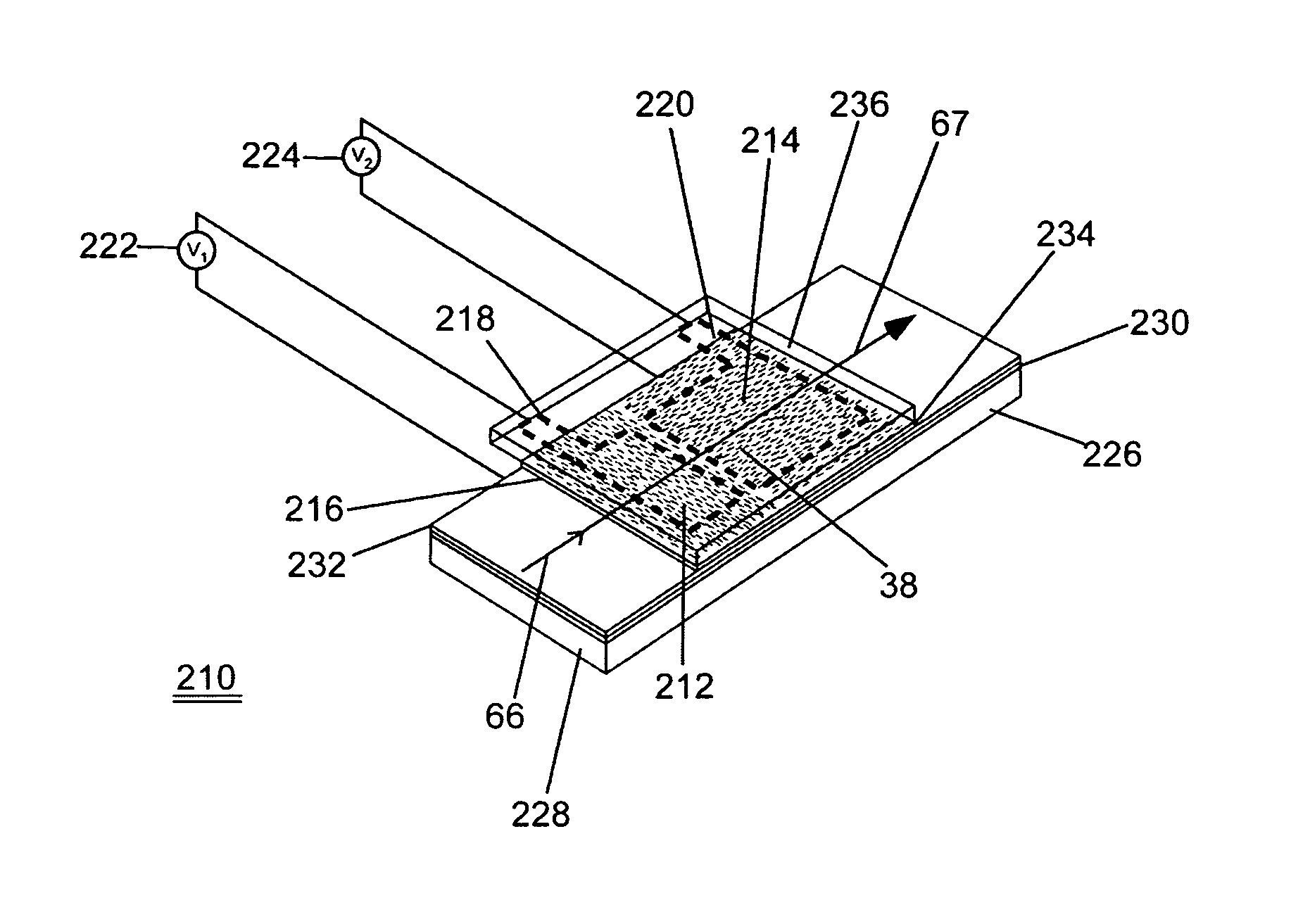
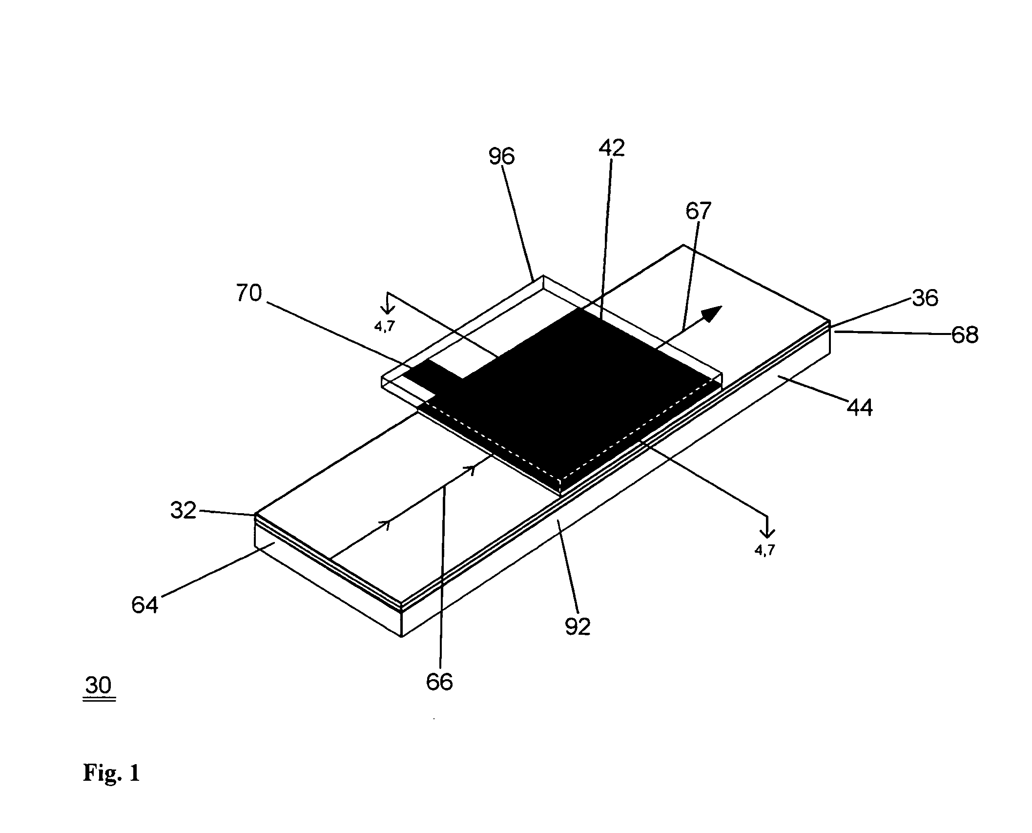
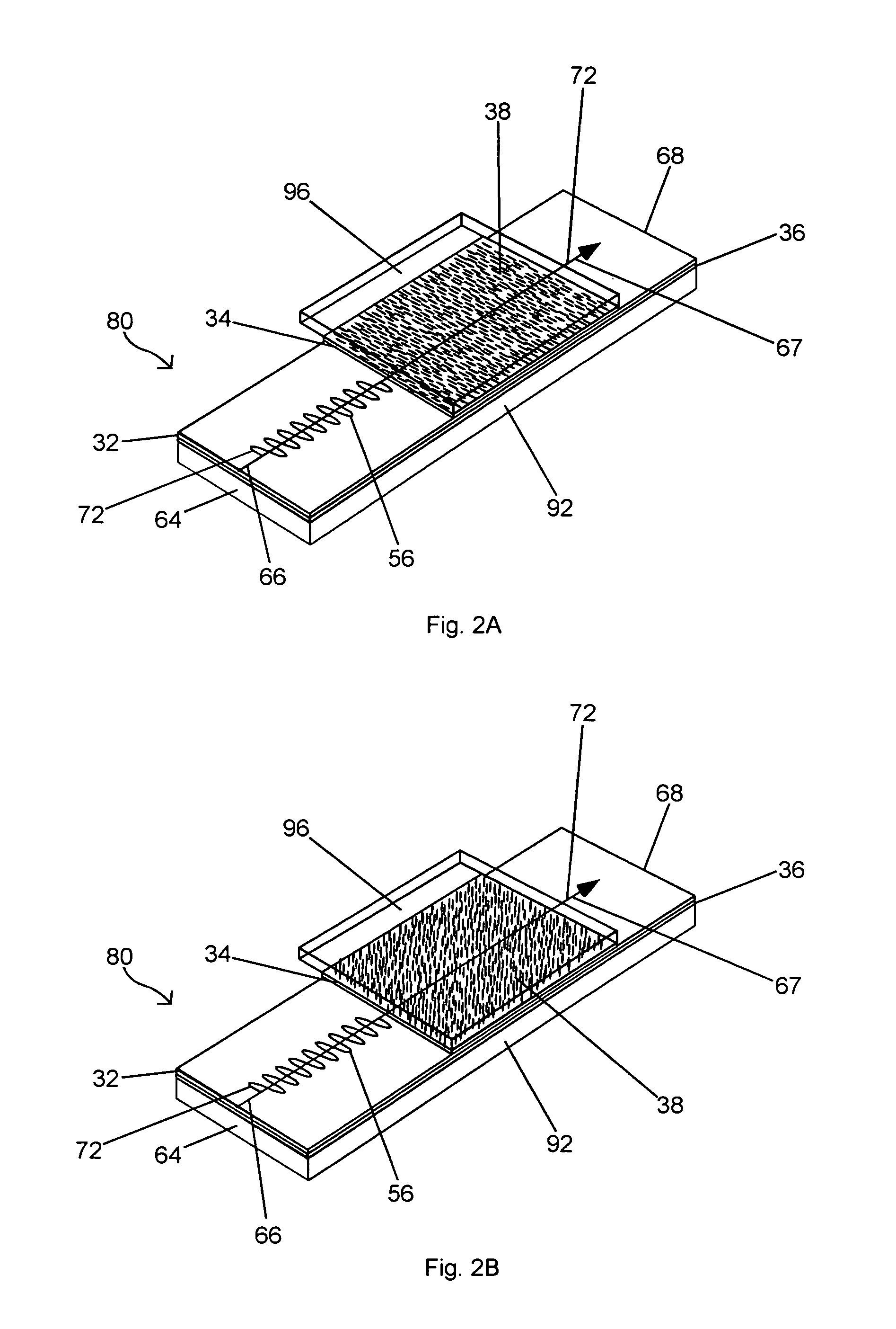
[0143]Described below is one example of a liquid crystal waveguide in which the waveguide was designed to provide for increased tunability of the TE vs. TM optical phase delay, and this is described as an example only. Furthermore, the waveguide was designed such that for all voltages of operation, the geometric birefringence was larger than the material birefringence. It is understood that this example is provided for illustrative purposes only, and does not limit the scope of embodiments of the present invention. In one example, a waveguide device may be formed utilizing a heavily p-doped silicon wafer, with both sides polished, as the lower electrode. Upon the p-doped silicon wafer, a thermally oxidized lower cladding can be grown with a thickness of 2±0.05 microns. The lower cladding refractive index at a wavelength of 1550 nanometers was 1.445±0.001 as measured by a broadband ellipsometer. A SiOxNy guide layer or core was applied over the lower cladding by plasma enhanced chemi...


PUM

PropertyMeasurementUnit
alternating current voltagesaaaaaaaaaa
temperatureaaaaaaaaaa

Abstract

A waveguide and method for controllably altering an optical phase delay (OPD) of light traveling along a propagation direction through the waveguide. Many embodiments are disclosed, and in one example, a waveguide may include a core for guiding the light through the waveguide; at least one cladding adjacent the core, wherein the at least one cladding has liquid crystal molecules disposed therein; at least one electrode for receiving a first voltage for controllably altering the optical phase delay of the TE polarized light traveling through the waveguide; and at least one electrode for receiving a second voltage for controllably altering the optical phase delay of the TM polarized light traveling through the waveguide.

Description

CROSS-REFERENCE TO RELATED APPLICATION[0001]This application is a continuation-in-part of U.S. patent application Ser. No. 11 / 396,313 entitled “LIQUID CRYSTAL WAVEGUIDE HAVING ELECTRIC FIELD ORIENTATED FOR CONTROLLING LIGHT” filed Mar. 30, 2006, which is a continuation-in-part of U.S. patent application Ser. No. 11 / 313,540 entitled “LIQUID CRYSTAL WAVEGUIDE FOR DYNAMICALLY CONTROLLING POLARIZED LIGHT” filed Dec. 20, 2005, which is a continuation-in-part of U.S. patent application Ser. No. 10 / 963,946 entitled “LIQUID CRYSTAL WAVEGUIDE HAVING REFRACTIVE SHAPES FOR DYNAMICALLY CONTROLLING LIGHT” filed Oct. 12, 2004, which claimed the benefit under 35 U.S.C. 119(e) to U.S. Provisional patent application No. 60 / 539,030 entitled “LIQUID CRYSTAL WAVEGUIDE HAVING REFRACTIVE SHAPES FOR DYNAMICALLY CONTROLLING LIGHT AND TUNABLE LASER INCLUDING SAME” filed Jan. 22, 2004, the disclosures of which are hereby incorporated by reference in its entirety.FIELD OF THE INVENTION[0002]This invention rel...

Claims


Application Information

Patent Timeline
Patent Type & Authority Patents(United States)
IPC IPC(8): G02F1/35
CPCG02F1/1396G02F2001/134381G02F2203/50G02F1/134381
Inventor ANDERSON, MICHAEL H.ROMMEL, SCOTT D.DAVIS, SCOTT R.
Owner ANALOG DEVICES INC
Why Eureka
Try Eureka