

Reclaim chemistry
Patent Information
- Authority / Receiving Office
- US · United States
- Current Assignee / Owner
- LAM RES CORP
- Publication Date
- 2013-06-18
- Estimated Expiration
- Not applicable · inactive patent
Smart Images
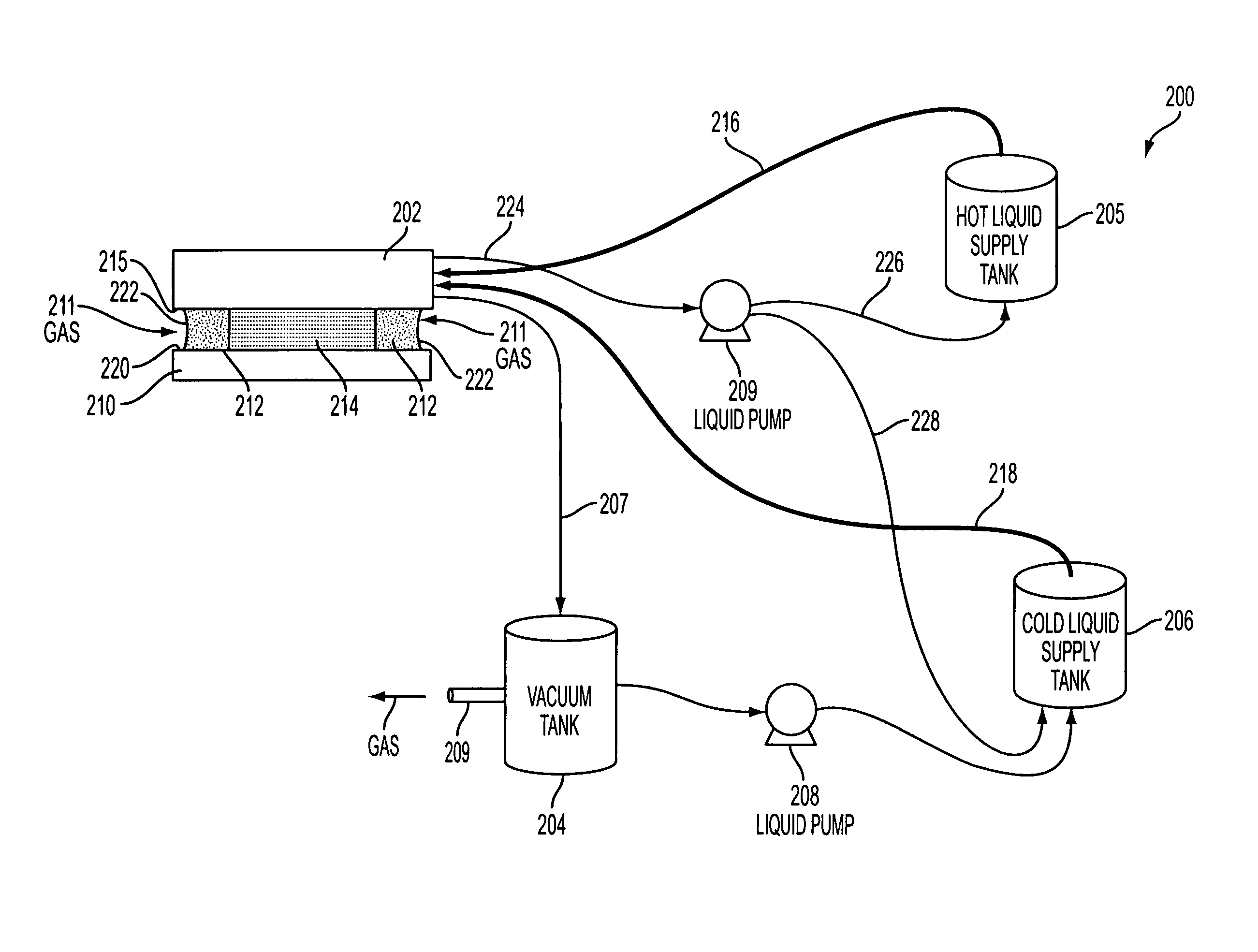
Figure 1 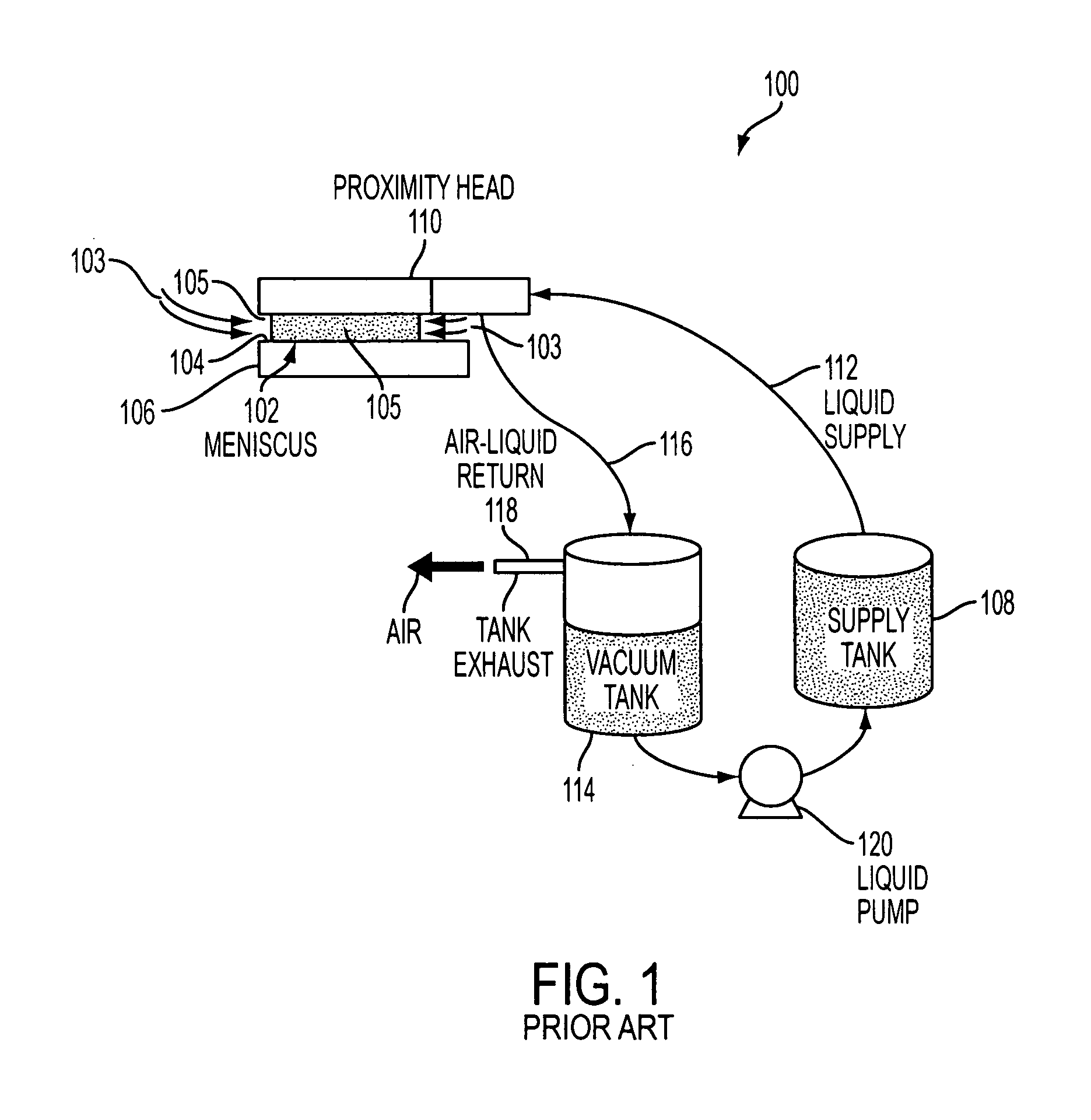
Figure 2 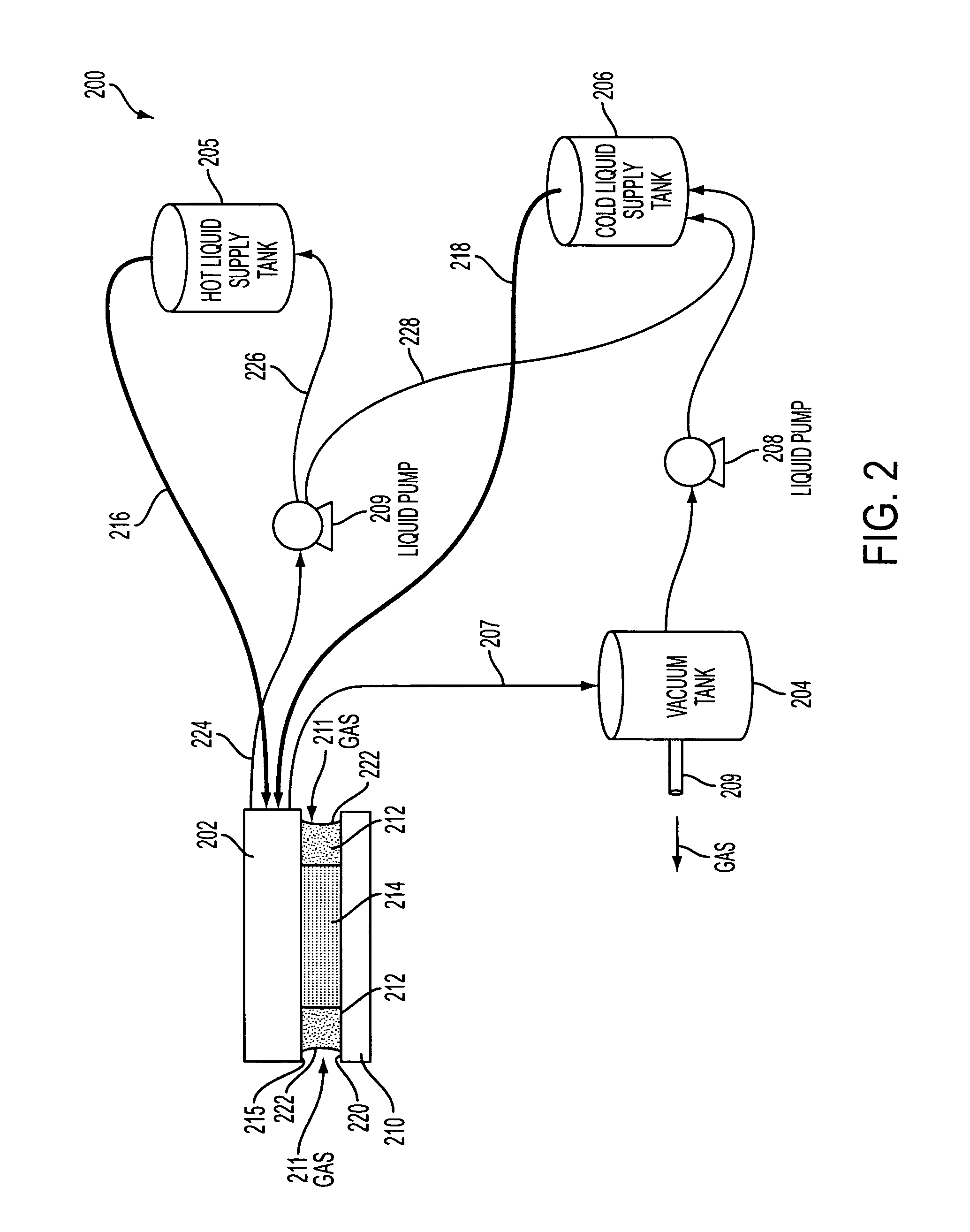
Figure 3
Abstract
Description
BACKGROUND
[0001] 1. Field of the Invention
[0002] The invention relates generally to semiconductor wafer processing and, more particularly, to apparatus and methods for eliminating chemical loss during the processing of semiconductor wafer surfaces.
[0003] 2. Description of the Related Art
[0004] In electronic device manufacturing operations, expensive proprietary chemical mixtures or blends customarily referred to as “solvents” or “proprietary solvents” are widely used to remove particulate contaminants, post-etch residue, and metal contamination from semiconductor wafer surfaces and to etch, rinse, dry, etc. semiconductor wafer surfaces. Such chemical solvents generally fall into two generic classes: “aqueous-based” solvents and “organic-based” solvents. Aqueous-based solvents are processing chemistries which are water-based (i.e. are up to 95% water by weight with the active chemical agents making up the remainder). Organic-based solvents are processing chemistries for which water is re...