
Rear structure of straddle-ride type vehicle

a rear structure and straddle-ride technology, applied in the direction of roofs, cycle equipment, cycles, etc., can solve the problem of reducing the negative pressure area to the rear of the vehicle, and achieve the effect of reducing the negative pressure area

Active Publication Date: 2013-06-18
HONDA MOTOR CO LTD
View PDF10 Cites 5 Cited by
  • Summary
  • Abstract
  • Description
  • Claims
  • Application Information

AI Technical Summary

Benefits of technology

[0008]The present invention has been made in view of such situations and aims to provide a rear structure of a straddle-ride type vehicle that can achieve a reduction in the negative-pressure area to the rear of the vehicle, the vehicle having a tire wholly covered from the left, right and back.
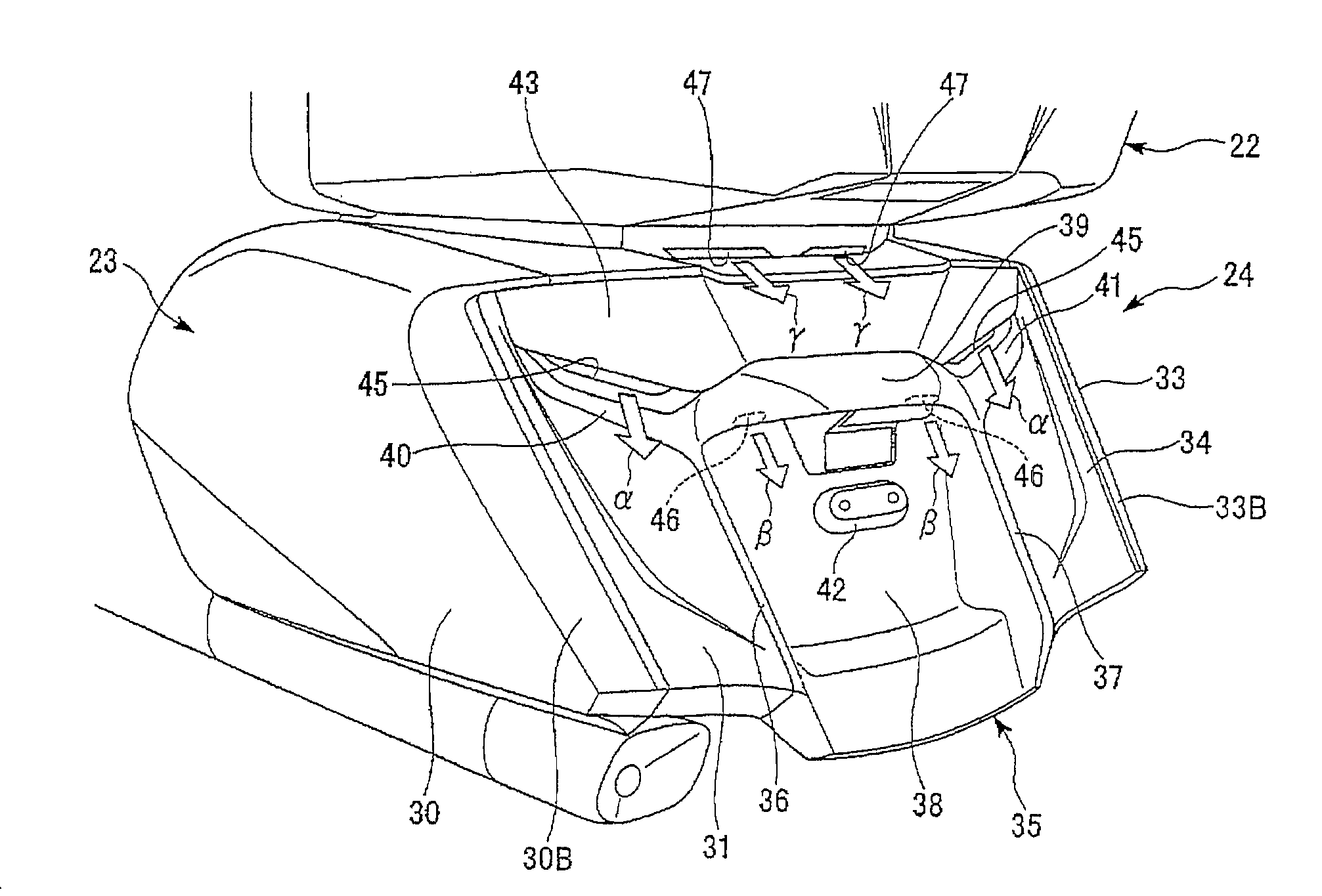
[0014]According to an embodiment of the present invention, the air in the rear wheel tire house, i.e., in the rear fender can be led toward the center of the negative pressure area (the turbulence zone) to the rear of the vehicle. Therefore, the negative pressure area to the rear of the vehicle can be reduced. The reduced inner pressure in the rear wheel tire housing can increase the grounding load of the rear tire to improve the grip force of the tire. Further, air can be passed through the tire housing covered by the cover to thereby cool the brake disk.
[0015]According to an embodiment of the present invention, the negative pressure correction hole is provided between the rear fender and the lighting unit. Therefore, the negative pressure correction hole can be made inconspicuous. Thus, the degree of freedom of design can be improved.
[0016]According to an embodiment of the present invention, air is led along the rear side of the eave portion. Therefore, air can be led toward the center of the negative pressure area. Thus, the negative pressure area can be reduced effectively. Since the negative pressure correction hole is provided at a place hidden by the eave portion, it can be made inconspicuous. Thus, the degree of freedom of design can be improved.
[0017]According to an embodiment of the present invention, since the negative pressure correction hole can be provided inconspicuously, the degree of freedom of design can be improved. More specifically, for example, in the case where the central trunk is shaped to protrude rearwardly, if the negative pressure correction hole is provided at a deep portion between the central trunk and the rear fender, the negative pressure correction hole can be made inconspicuous. Thus, the degree of freedom of design can be improved.
[0018]According to an embodiment of the present invention, pressure concentration at front portions of the left and right trunks due to a flow of air can be reduced. Therefore, travel resistance can be reduced. Since the pressure-receiving area is reduced, yawing moment applied to the vehicle body due to side wind can be reduced.

Problems solved by technology

In addition, the vehicles whose tire is wholly covered from the left, right and back as described above tend to enlarge a negative-pressure area (turbulence zone) to the rear of the vehicle.
Therefore, there arises a problem with a reduction in the negative-pressure area to the rear of the vehicle.

Method used


Image

  • Rear structure of straddle-ride type vehicle
  • Rear structure of straddle-ride type vehicle
  • Rear structure of straddle-ride type vehicle

Examples


Embodiment Construction

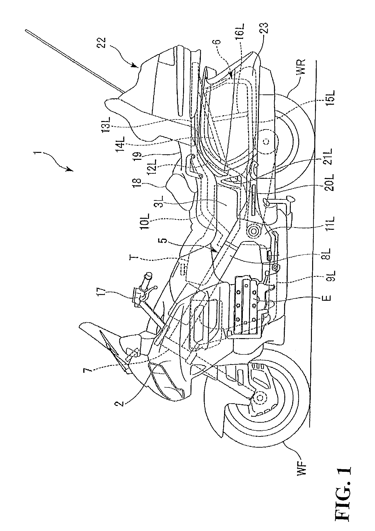
[0028]An embodiment of the present invention will hereinafter be described with reference to the drawings. There is illustrated a motorcycle 1 provided with a structure according to the present invention in FIG. 1.

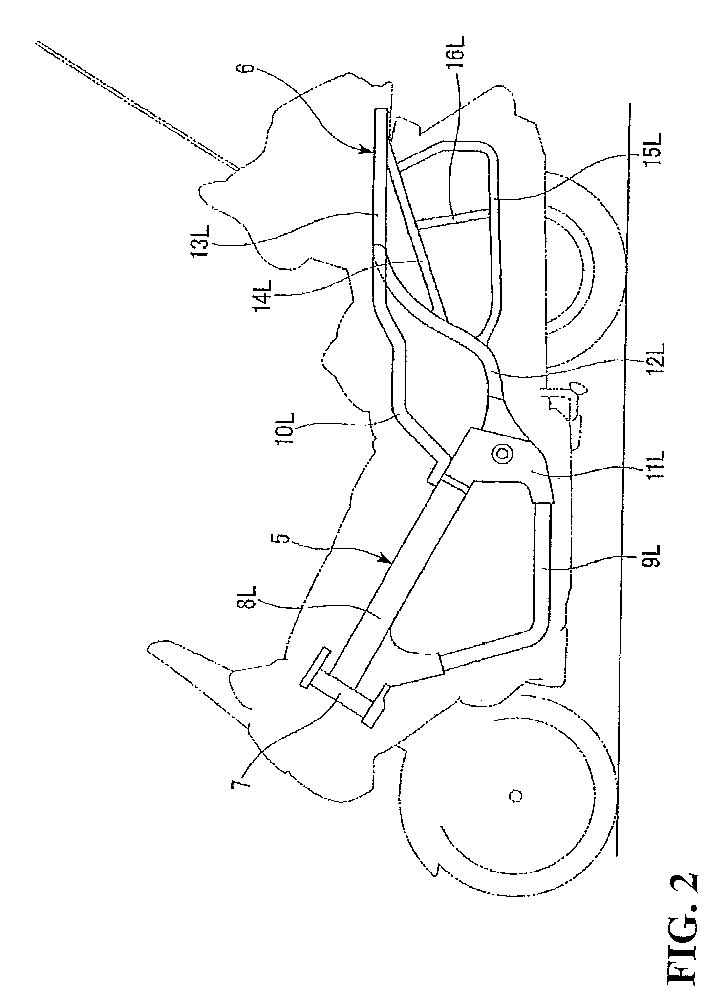
[0029]The motorcycle 1 illustrated in FIG. 1 includes an engine E between front and rear wheels WF, WR and is such that a front portion of a vehicle body is covered by a front body cover 2 and left and right lateral surfaces of the vehicle body are respectively covered by side body covers 3L, 3R (only the side body cover 3L on the front side of the paper surface is illustrated). With reference to FIG. 2, a body frame 4 forming a basic skeleton of the vehicle body of the motorcycle 1 is composed of a body frame main body 5 and a rear body frame 6.

[0030]The body frame main body 5 includes a head pipe 7; a pair of left and right main frames 8L, 8R joined to the head pipe 7 and extending toward the rear of the vehicle body in a tilted posture; a pair of left and right down fra...


PUM


Abstract

In a vehicle whose tire is wholly covered from the left, right and back, a negative pressure area to the rear of the vehicle is reduced. In a vehicle including a left trunk and a right trunk in a rear portion of the vehicle, a rear fender continuous with respective rear faces of the left and right trunks is provided, and a plane formed of the respective rear faces of the left and right trunks and the rear fender is provided with negative pressure correction holes.

Description

CROSS-REFERENCE TO RELATED APPLICATIONS[0001]The present application claims priority under 35 USC 119 to Japanese Patent Application No. 2009-277546 filed on Dec. 7, 2009 the entire contents of which are hereby incorporated by reference.BACKGROUND OF THE INVENTION[0002]1. Field of the Invention[0003]The present invention relates to a rear structure of a straddle-ride type vehicle.[0004]2. Description of Background Art[0005]Many vehicles such as relatively large-sized scooter-type or cruiser-type motorcycles are such that a tire is wholly covered from the left, right and back. For example, Japanese Patent Laid-open No. 2006-44539 discloses a motor-driven two-wheeled vehicle whose tires are wholly covered from the left, right and back. This vehicle is provided with air flow outlets at positions to the rear of a storage box below a seat and of auxiliary machinery covers on the sides of the seat. Auxiliary machinery is installed in each of the auxiliary machinery covers. In this way, ai...

Claims


Application Information

Patent Timeline
Patent Type & Authority Patents(United States)
IPC IPC(8): B62D61/02
CPCB62K19/46B60K11/06
Inventor HAYASHI, KANJINAKANISHI, RYUICHIINOUE, YOSHIHIROKAJITORI, KYOTAROOMAE, AKIRAKATO, TAKAAKI
Owner HONDA MOTOR CO LTD
Learn More