
Methods for forming ignitable heterogeneous structures

a heterogeneous structure and ignitable technology, applied in the field of composite material structures, can solve the problems of negate the energy density advantage of inorganic energetic materials, and the extent or quality of vacuum present in such chambers is never per

Active Publication Date: 2013-06-18
UNIV OF CENT FLORIDA RES FOUND INC
View PDF5 Cites 8 Cited by
  • Summary
  • Abstract
  • Description
  • Claims
  • Application Information

AI Technical Summary

Benefits of technology

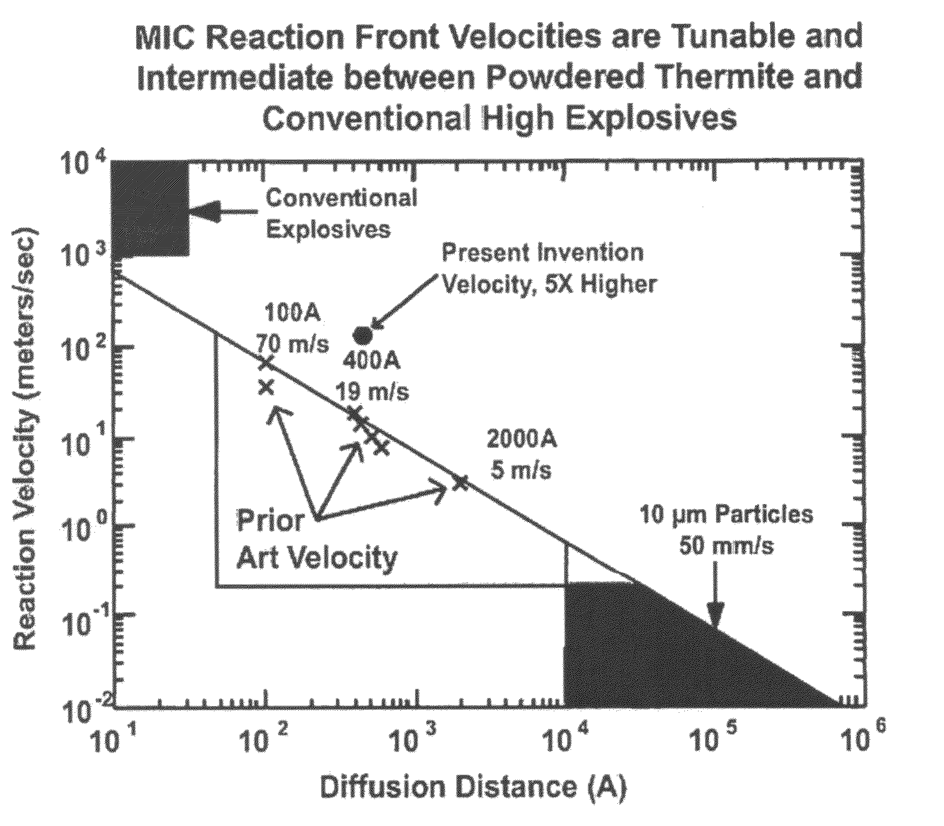
[0014]Embodiments of the present invention are based on the unexpected discovery by the Inventors that the average thickness of the interfacial region over the entire interface area can be reduced to averaging <2 nm thick, typically averaging <1 nm thick, and still provide substantially the same level of stability against unintentional initiations provided by convention thicker interfacial regions (e.g. >2 to 5 nms, or more). MICs having a reduction in the thickness of the interfacial region according to embodiments of the invention have been found to perform quite differently as compared to known MICs. For example, as described below, the reaction velocity for MICs according to embodiments of the invention are generally increased by a factor of five (5) or more as compared to conventional MICs. Accordingly, MICs according to embodiments of the invention having an average thickness of the interfacial region over the entire interface area reduced to <2 nm thick evidence criticality, provide an unexpected result, and perform quite differently (e.g. significantly better reaction velocity) as compared to known MICs.

Problems solved by technology

Loose powders typically have densities that are only 5% to 10% of the TMD, and thus negate the energy density advantage of the inorganic energetic materials.
The extent or quality of the vacuum present in such chambers is never perfect, and residual traces of certain contaminant gases are generally always present.

Method used


Image

  • Methods for forming ignitable heterogeneous structures
  • Methods for forming ignitable heterogeneous structures
  • Methods for forming ignitable heterogeneous structures

Examples


examples

[0032]It should be understood that the Examples described below are provided for illustrative purposes only and do not in any way define the scope of the invention.

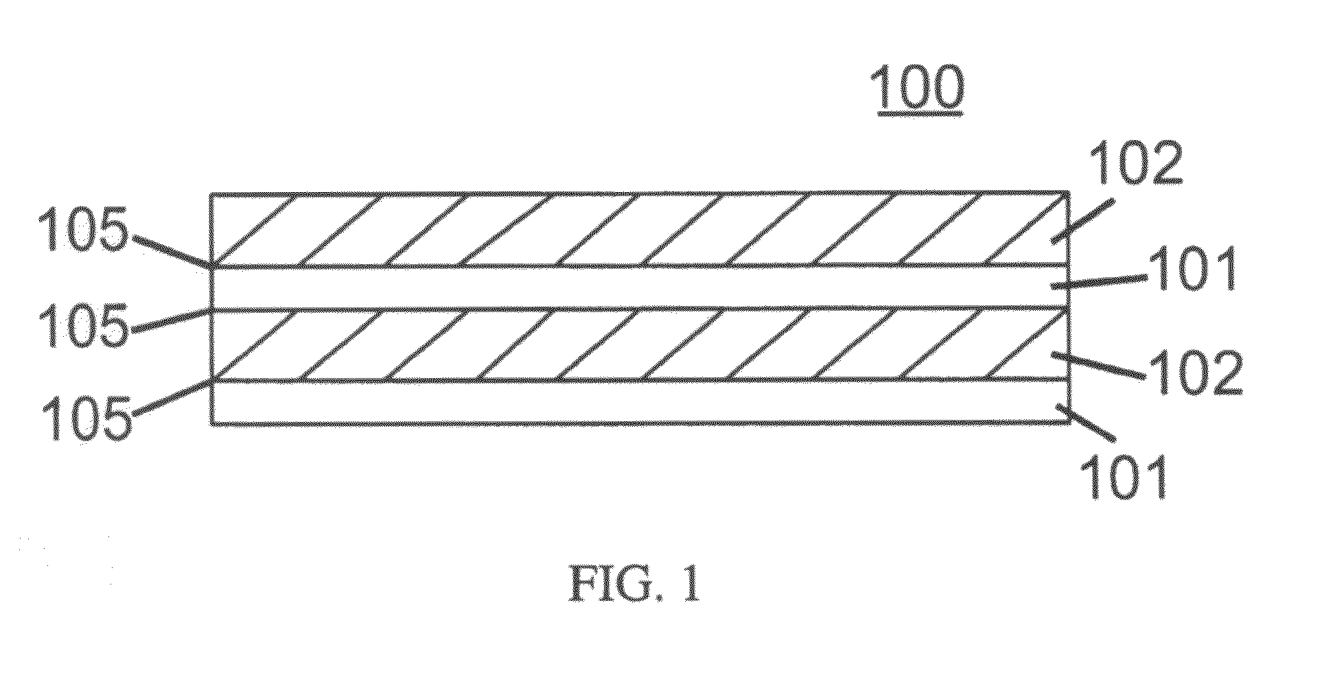
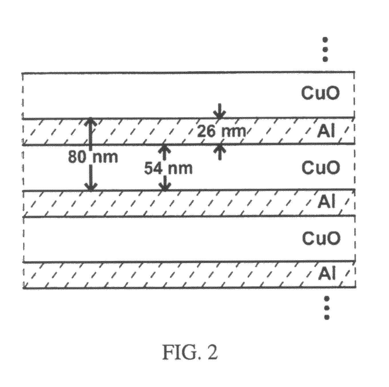
[0033]The specific example described herein comprised an Al / copper oxide (CuO) multilayered MIC sample (comprising typically 40, 20, or 10 pairs of alternating Al and copper oxide layers) having a total thickness of approximately 3.2 microns, prepared by magnetron sputter deposition. The deposition was an automated deposition. The sputter targets comprised a CuO target and an Al target.

[0034]The processing conditions comprised a chamber base pressure −8 Torr, such as ≦6×10⁻⁹ Torr, with the Ar sputter gas gettered with a hot reactive metal gettering device to remove substantially all the moisture. The sputter chamber was conditioned for several days before forming the MIC, and included a conditioning deposition with a layer of Ti prior to the deposition of the MIC on the substrate. An example of a conditioning deposition o...


PUM

PropertyMeasurementUnit
base pressureaaaaaaaaaa
thickaaaaaaaaaa
thickaaaaaaaaaa

Abstract

A method for forming a metastable intermolecular composite (MIC) includes providing a vacuum level of <10−8 torr base pressure in a deposition chamber. A first layer of a first material of a metal that is reactive with water vapor is deposited, followed by depositing a second layer of a second material of a metal oxide on the first layer. The first and second material are capable of an exothermic chemical reaction to form at least one product, and the first and second layer are in sufficiently close physical proximity so that upon initiation of the exothermic reaction the reaction develops into a self initiating chemical reaction. An interfacial region averaging <1 nm thick is formed between the first layer and second layer from a reaction of the first material with water vapor. In one embodiment, the first material is Al and the second material is CuOx.

Description

CROSS REFERENCE TO RELATED APPLICATIONS[0001]This application is a divisional application of U.S. non-provisional patent application Ser. No. 12 / 398,228 entitled “IGNITABLE HETEROGENEOUS STRUCTURES AND METHODS FOR FORMING”, filed Mar. 5, 2009, now U.S. Pat. No. 8,298,358, which claims priority to Provisional Application Ser. No. 61 / 034,825 entitled “IGNITABLE HETEROGENEOUS STRUCTURES AND METHODS FOR FORMING”, filed on Mar. 7, 2008, both of which are incorporated herein by reference in their entirety into this application.FEDERAL RIGHTS[0002]The U.S. Government may have certain rights to the invention based on Contract No. FA95500710349 with the Air Force Office of Scientific Research (AFOSR).FIELD OF THE INVENTION[0003]Embodiments of the invention relate to composite material structures that can sustain the self-propagating reactions and related ignitable structures.BACKGROUND[0004]A composite structure that can sustain a self-propagating reaction is commonly referred to as a metast...

Claims


Application Information

Patent Timeline
Patent Type & Authority Patents(United States)
IPC IPC(8): D03D43/00
CPCC06B33/00C06B45/14
Inventor COFFEY, KEVIN R.DEIN, EDWARD ALANYAO, BO
Owner UNIV OF CENT FLORIDA RES FOUND INC
Learn More