Calibration of a base coordinate system for an industrial robot

Active Publication Date: 2013-06-18
ABB (SCHWEIZ) AG
View PDF24 Cites 5 Cited by
  • Summary
  • Abstract
  • Description
  • Claims
  • Application Information

AI Technical Summary

Benefits of technology

[0014]One object of the present invention is to provide a fast and a

Problems solved by technology

A common situation, especially in smaller enterprises, is that robot automation is not affordable because robots can not move between different machines as flexible as a human worker.
Sometimes it is possible to mount the robot hanging on linear guide ways or standing on floor-mounted guide ways, but this kind of solution is expensive and can be difficult to install in the workshop.
A problem with moving a robot between different work areas is that the position and orientation of the robot with respect to the work area must be determined with a high accuracy each time the robot has been moved to a work area.
Concepts presented so far to solve this problem are too complicated with special docking mechanisms, docking sensors and even navigation systems.
There is also the cost problem when too complex platforms are used, including safety sensors, high precision docking mechanisms, docking sensors etc.
The most important reason why portable robots have not yet been introduced is that the concepts presented so far do not solve the problem of how to reduce the time between the docking of the robot and the execution of the robot programs.
A basic problem in robot installations and commis

Method used


Image

  • Calibration of a base coordinate system for an industrial robot
  • Calibration of a base coordinate system for an industrial robot
  • Calibration of a base coordinate system for an industrial robot

Examples


Embodiment Construction

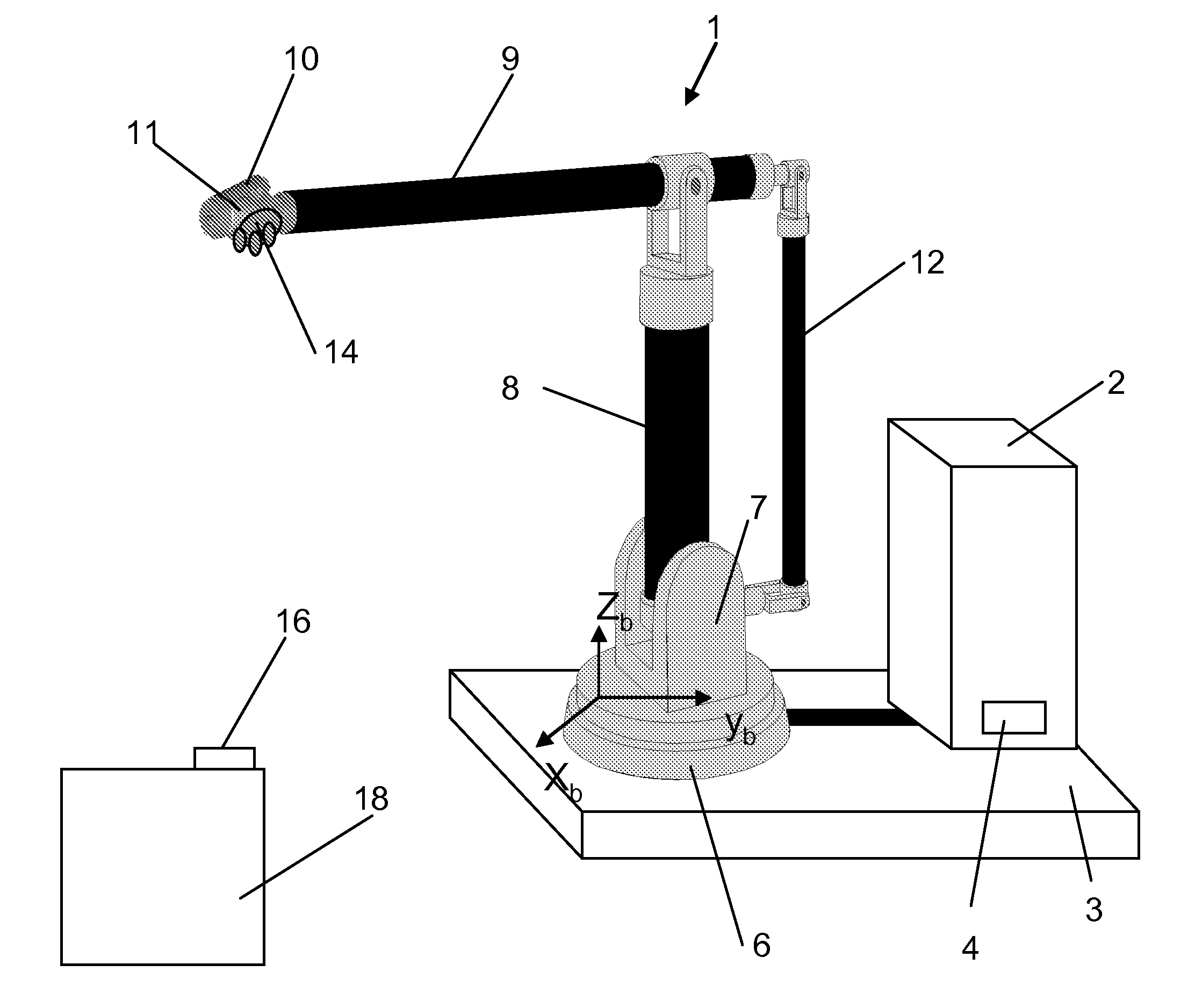
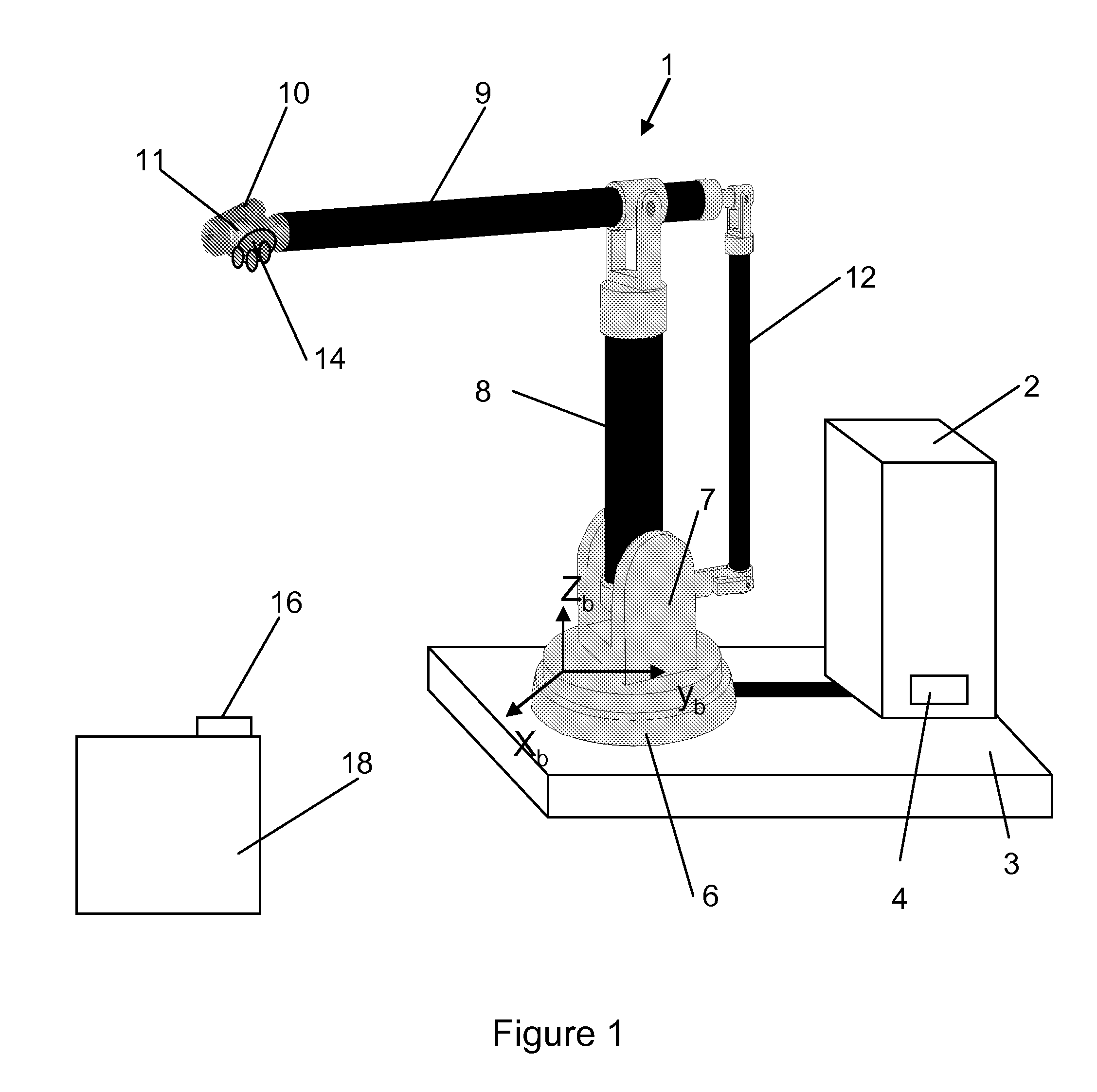
[0057]FIG. 1 exemplifies a portable robot, where a lightweight robot 1 including a robot controller 2 is mounted on a movable platform 3. The portable robot is located in a robot cell which defines a work area for the robot. The robot controller 2 is also mounted on the platform but there are cases when each robot cell may have its own controller and then only the robot will be on the platform. The robot 1 is connected to the controller 2 by a cable and at docking a contact 4 is used to electrically connect the robot, tools, and the controller to the cell. The robot comprises a stationary base part 6, which supports a stand 7 that is rotatable about a first axis. The stand 7 supports a lower arm 8 that is rotatable about a second axis. The lower arm 8 supports an upper arm 9, which is rotatable about a third axis. The upper arm 9 supports a wrist 10 that is rotatable about a fourth, a fifth and a sixth axis. The wrist 10 supports a wrist interface 11 in the following named a wrist f...


PUM


Abstract

A method for calibration of a base coordinate system of an industrial robot in relation to a work area includes:
    • mounting a first part of a kinematic coupling which is constrained in the same number of degrees of freedom as the robot, on the robot wrist interface of the robot,
    • mounting a second part of the kinematic coupling in the work area,
    • moving the robot including the base portion to the work area,
    • set the robot in compliant control mode,
    • move the first part of the kinematic coupling to mate with the second part,
    • storing axis positions of the robot during mating of the kinematic coupling,
    • determining the position and orientation of the base portion based on the stored axis positions and a kinematic model of the robot, and on basis thereon calibrating the base coordinate system of the robot.

Description

CROSS-REFERENCE TO RELATED APPLICATIONS[0001]The present application is a continuation of pending International patent application PCT / EP2010 / 053518 filed on Mar. 18, 2010 which designates the United States and the content of which is incorporated herein by reference.FIELD OF THE INVENTION[0002]The present invention relates to a method for calibration of a base coordinate system of a robot in relation to a work area.[0003]The present invention also relates to a kinematic coupling for calibration of a base coordinate system of a robot.BACKGROUND OF THE INVENTION[0004]The invention is particularly useful for calibration of a portable robot. With a portable robot is meant a robot which is mobile of its own or is movable by other means, such as a truck. A work area is a place at which the robot shall carry out work, for example, a robot cell. For example, the work area includes work objects and / or workstations on which the robot is to carry out work.[0005]A robot includes a base portion...

Claims


Application Information

Patent Timeline
IPC IPC(8): G05B19/18G05B19/04
CPCB25J9/1692G05B2219/39027G05B2219/39032
Inventor BROGARDH, TORGNY
Owner ABB (SCHWEIZ) AG
Why Eureka
Try Eureka