Drive arrangement for an inboard-outboard drive engine of a watercraft

a technology of drive arrangement and watercraft, which is applied in the direction of marine propulsion, propulsion transmission, vessel construction, etc., can solve the problems of adversely affecting the sealing properties of the watercraft, the reaction force and torque in all directions, and achieve the effect of increasing the rigidity of the carrier arms, reducing the weight, and reducing the weigh

Inactive Publication Date: 2013-06-25
ZF FRIEDRICHSHAFEN AG
View PDF19 Cites 0 Cited by
  • Summary
  • Abstract
  • Description
  • Claims
  • Application Information

AI Technical Summary

Benefits of technology

[0007]The invention is based on the technical principle that the upper part of the drive unit is in contact with a carrier system which, by virtue of a plurality of support units, supports reaction forces and torques imposed upon the drive unit in longitudinal, transverse and vertical directions relative to the hull when the watercraft is driven. Since by virtue of the carrier system and its supporting units all reaction forces and torques are absorbed directly and transferred to the hull of the watercraft, in the area of the opening in the hull the seal can be designed optimally in relation to its sealing function. Moreover, in this way the load on the drive engine mountings is substantially reduced.
[0015]In a further development of the invention two propellers are provided on the lower part of the drive unit, which rotate in opposite directions when the watercraft is driven. By virtue of the oppositely rotating propellers rotation losses can be eliminated and cavitation effects minimized. Furthermore, no undesired lateral forces are produced and the bigger blade area enables larger gear steps in the drive to be used.

Problems solved by technology

However, this drive arrangement of the prior art has the considerable disadvantage that reaction forces and torques in all other directions are not taken up by the rubber mounting acting on one side, but have to be absorbed by an engine mounting and by the seals.
As a result the seal between the drive unit and the hull has to be made more rigid in order to be able to absorb the loads and vibrations over a long time without problems, but this at the same time adversely affects its sealing properties.

Method used


Image

  • Drive arrangement for an inboard-outboard drive engine of a watercraft
  • Drive arrangement for an inboard-outboard drive engine of a watercraft
  • Drive arrangement for an inboard-outboard drive engine of a watercraft

Examples


Embodiment Construction

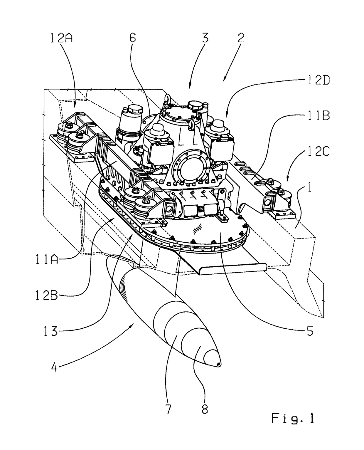
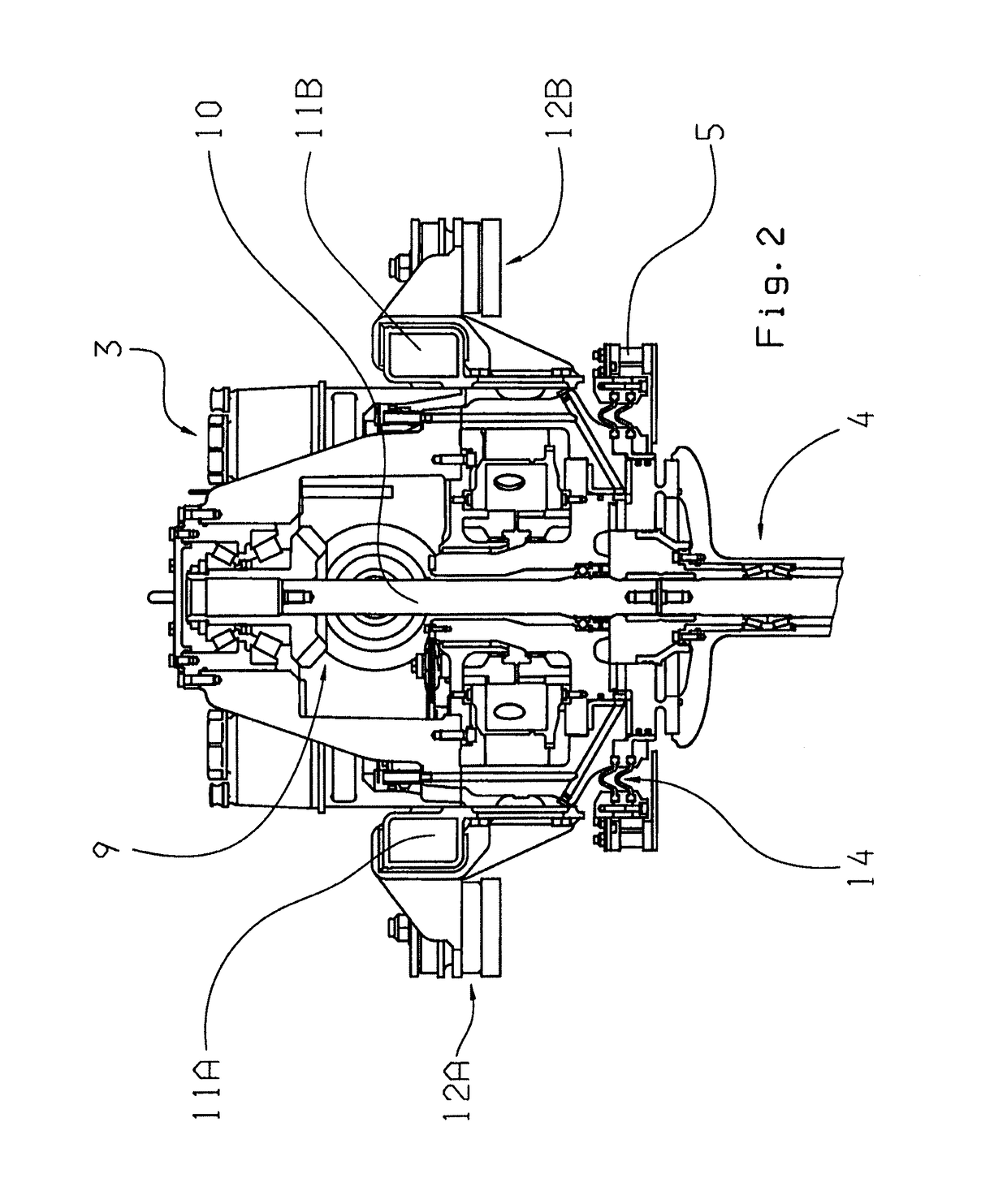
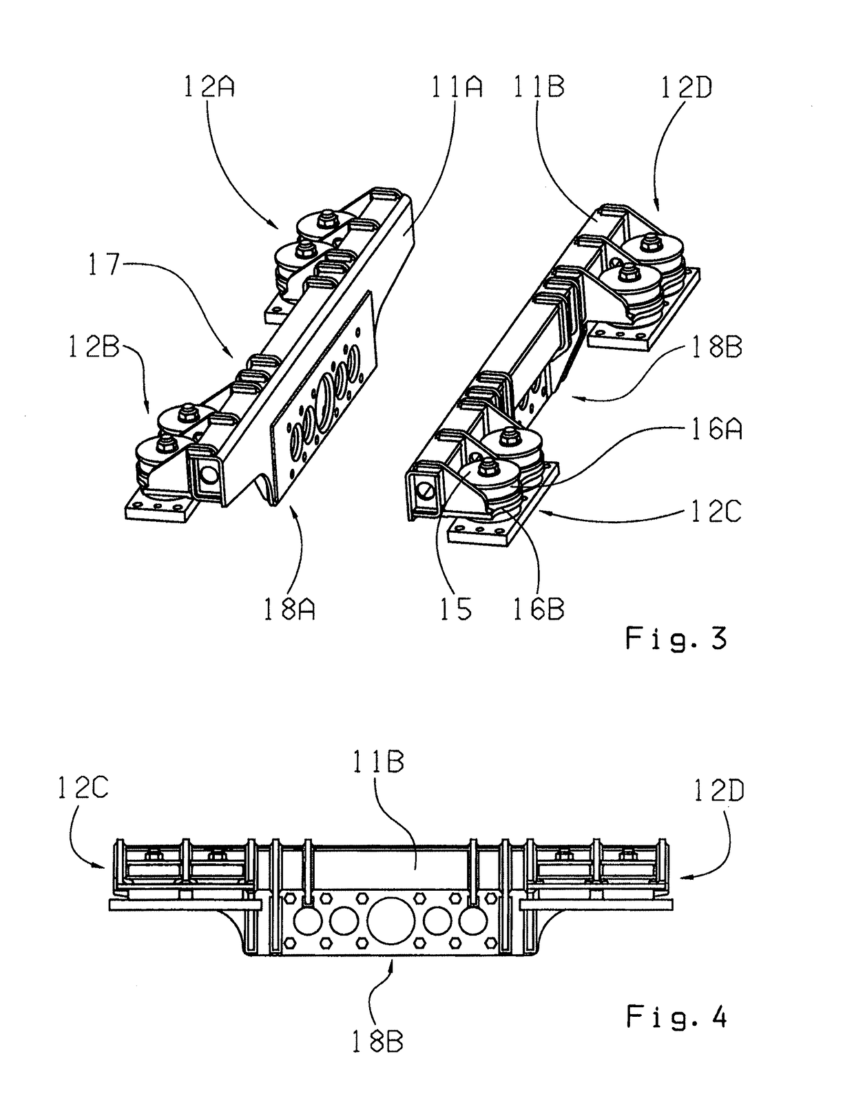
[0021]FIG. 1 shows a perspective view of the drive arrangement according to the invention, in the area of a hull 1 of a watercraft. This drive arrangement comprises a drive unit 2 consisting of an upper part 3 and a lower part 4, which is carried by a plate arrangement 5 in an opening of the hull 1. The upper part 3 of the drive unit 2 is arranged within the hull 1 and, in the longitudinal direction, is connected on one side to a motor (not shown here) of the watercraft by means of a flange 6 only partially visible in this view. Starting from the opening in the hull 1 the lower part 4 of the drive unit 2 projects into the water surrounding the watercraft and carries drive hubs 7 and 8 of two propellers (also not shown here). Rotational movement introduced by the flange 6 is transmitted within the drive unit 2 to the lower part 4 by a bevel gear transmission 9 (only visible in the side view shown in FIG. 2) of a drivetrain passing through the drive unit 2, by means of a vertically ex...


PUM


Abstract

A drive arrangement for an inboard-outboard drive engine of a watercraft, comprising a drive unit (2) with an upper part (3) arranged in a hull (1) of the watercraft and a lower part (4) which projects through a sealed opening in the hull (1) into the surrounding water such that a drivetrain extends through the drive unit (2). At least one propeller is supported by the lower part (4) and can be driven by a motor coupled to drive the upper part (3). The upper part (3) is in contact with a carrier system which, by virtue of a plurality of supporting units (12A-12D), supports reaction forces and torques produced in the drive unit (2) in the longitudinal, transverse and vertical directions relative to the hull (1).

Description

[0001]This application is a National Stage completion of PCT / EP2010 / 051700 filed Feb. 11, 2010, which claims priority from German patent application serial no. 10 2009 000 996.5 filed Feb. 18, 2009.FIELD OF THE INVENTION[0002]The invention concerns a drive arrangement for an inboard-outboard drive engine of a watercraft, comprising a drive unit with an upper part arranged in a hull of the watercraft, and a lower part which projects into the surrounding water through a sealed opening in the hull, such that a drivetrain extends through the drive unit, by reasons of which at least one propeller provided on the lower part can be driven by an engine located in the area of the upper part.BACKGROUND OF THE INVENTION[0003]In watercraft, in particular engine-driven speedboats, drive concepts are often used in which a drive engine of the watercraft is arranged inside the latter and is actively connected, via a drive unit in the area of the boat's hull, to one or more propellers. For this purp...

Claims


Application Information

Patent Timeline
Patent Type & Authority Patents(United States)
IPC IPC(8): B63H23/36
CPCB63H21/30
Inventor GALLATO, FERNANDOBERTOLO, ADONETOGNON, ANDREA
Owner ZF FRIEDRICHSHAFEN AG
Why Eureka
Try Eureka