Ultrasonic assembly with adjustable fluid lens

a technology of ultrasonic equipment and fluid lens, which is applied in the field of ultrasonic equipment, can solve the problems of reducing the conductive efficiency of tissue, requiring separate catheters and fixed inflatable balloons, and complicating therapy planning, etc., and achieves the effect of simple and economic us

Inactive Publication Date: 2013-07-02
KONINKLIJKE PHILIPS ELECTRONICS NV
View PDF14 Cites 16 Cited by
  • Summary
  • Abstract
  • Description
  • Claims
  • Application Information

AI Technical Summary

Benefits of technology

[0007]It is an object to provide a simple ultrasonic assembly capable of adjusting focus in 3D such as to allow ultrasonic therapy e.g. on pulmonary veins for treating atrial fibrillation, and to allow simple and economic use, one version of the assembly must be capable of fitting different vein sizes.
[0015]An ultrasonic assembly according to the first aspect is advantageous e.g. for ultrasonic therapy systems, such as for performing ultrasonic therapy on (the vicinity of) the pulmonary veins with the purpose of treating atrial fibrillation. Due to the adjustable fluid interface shape, the ultrasonic focus point can be adjusted in two perpendicular directions, and thus provide ultrasonic focusing controllable in three dimensions (3D). E.g. this can be made possible with embodiments with rotational symmetric focus lenses, where the fluid interface can be controlled such that ultrasonic focus point can be controlled both in a radial direction, i.e. in a direction perpendicular to the extension of the catheter axis, as well as in an elevation direction, i.e. in a direction along the extension of catheter. With such control of the ultrasonic focus point, full control of an ultrasonic therapy is possible, and it is possible to adjust the focus point at a considerable distance from an outer surface of the ultrasonic assembly. Thereby, it is possible that one size of the ultrasonic assembly can be used for treatment of pulmonary veins of different size, or in general treatment of ducts of different size, thus eliminating the need for a large range of assembly sizes to fit a specific patient.
[0016]Further, since the electric control circuit necessary to control the geometry of the fluid focus lens is rather simple, and the control can be designed such that only low voltages are involved, e.g. in the order of 10 V, such as 50-80 V. Thus, it is possible to use the assembly in ultrasonic therapy systems that can be implemented with low cost components. Still further, due to the precise 3D focus point control, the assembly enables shorter ultrasonic treatment periods, thus providing increased patient comfort as well as higher patient throughput with the same medical service personnel available. In atrial fibrillation therapy, the assembly also allows adjustment of the depth of field and position of the focus of the deposition of the ultrasonic energy to improve the alteration of the conduction pathways.
[0017]Still further, the ultrasonic assembly is advantageous for medical applications, since it can be implemented with first and second fluids that are non-toxic to the human body, and thus no serious harm is caused in case some fluid should accidentally leak when introduced in the human body. E.g. perfluorocarbons and water can be used as fluids for the fluid lens, since these fluids can both satisfy the technical and safety requirements.
[0019]In preferred embodiments, the assembly has a substantially rotational symmetric shape with the ultrasonic transducer placed in the centre. Such embodiments enable ultrasonic focus to occur in an annular ring around the centre of assembly, thus making the assembly useful for therapy of a vein which normally has a substantially circular cross section. Still, the annular ring shaped focus point can be obtained with a simple fluid focus lens with only one set of electrodes, and thus electrical control of such embodiment is simple.

Problems solved by technology

The resulting heat is absorbed by the tissue and results in tissue coagulation and scarring thereby reducing the conductive efficiency of the tissue.
The drawback to this design is that a separate catheter with a fixed inflatable balloon has to be used depending on the size of the pulmonary vein.
This complicates therapy planning, results in variable outcomes, and also introduces both manufacturing and inventory complications.
However, the combined use of a phased array and an adjustable liquid lens to obtain 3D focus control makes this ultrasonic device rather complicated.

Method used


Image

  • Ultrasonic assembly with adjustable fluid lens
  • Ultrasonic assembly with adjustable fluid lens
  • Ultrasonic assembly with adjustable fluid lens

Examples


Embodiment Construction

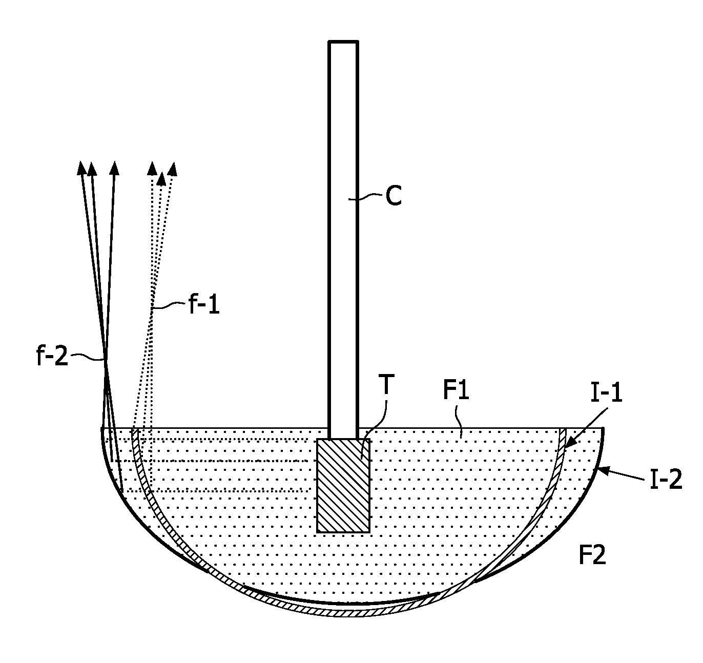
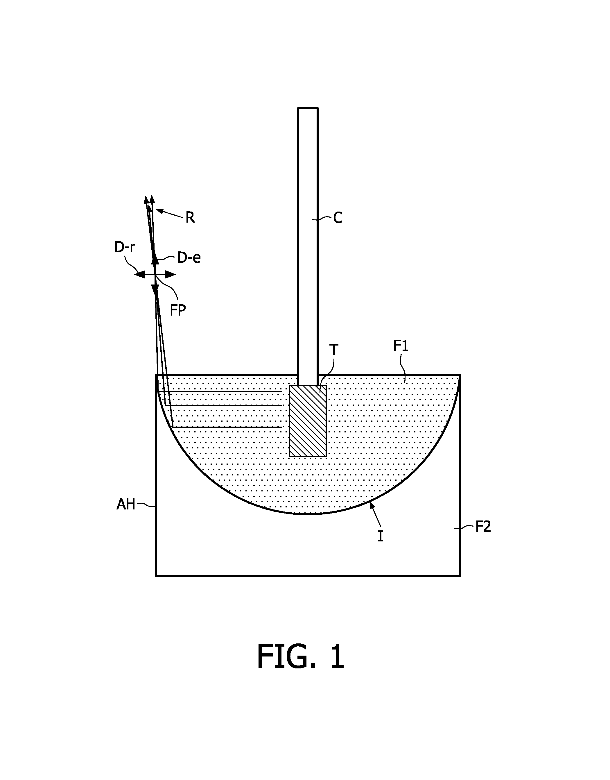
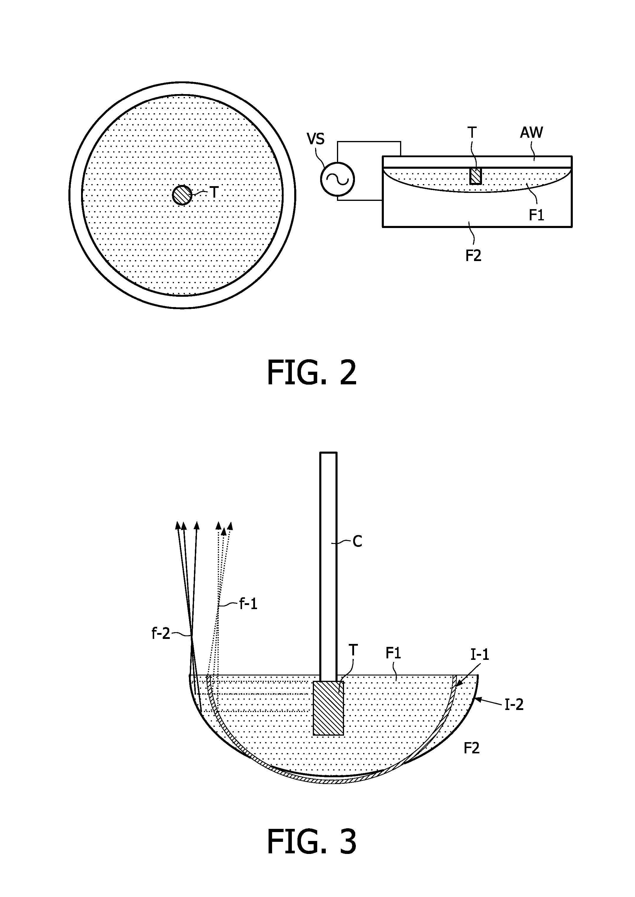
[0041]FIGS. 1 and 2 illustrate basic parts of a rather simple ultrasonic assembly embodiment such as for use in medical treatment, e.g. for insertion into human pulmonary veins. FIG. 1 illustrates a side view, while FIG. 2 illustrate a top view (to the left) seen from the catheter C side, and a side view illustrating a voltage source VS connected to control the single fluid focus lens in this embodiment.

[0042]In FIG. 1 the ultrasonic assembly embodiment is mounted on a catheter C such as for use in medical treatment. Electrical connections to the transducer and control signal(s) to control the fluid focus lens can be applied from outside via wires inside the catheter C. In the illustrated embodiment, the fluid focus lens formed by a first fluid F1 and a second fluid F2 arranged with an interface I between, has a shape being rotational symmetric around an axis formed by the extension of the catheter C. From FIG. 2 this is seen in the sketch to the left as a circular top section view ...


PUM


Abstract

An ultrasonic assembly suited for attachment to a catheter, e.g. for medical treatment. The ultrasonic assembly includes an adjustable ultrasonic focus mechanism arranged in connection with the ultrasonic transducer to adjust focus of ultrasonic waves generated by the transducer. The ultrasonic focus mechanism includes a fluid focus lens with at least two fluids separated by an interface such that ultrasonic waves are substantially reflected at the interface. At least two electrodes are arranged in connection with the fluid focus lens so as to allow adjustment of the interface shape, e.g. a curvature of the interface, when a voltage is applied to the electrodes. In preferred embodiments the electrodes are arranged so as to allow adjustment of the fluid focus lens in an elevation direction as well as in a radial direction. In simple embodiments with rotational symmetric geometry with the transducer positioned in the center of the fluid focus lens, ultrasonic waves can be focused in an annular ring. This is e.g. suitable for ablative or coagulative necrotic treatment of human tissue, e.g. for atrial fibrillation treatment. In some embodiments, the assembly has a number of separate individually adjustable fluid focus lens compartments allowing a more detailed control of the ultrasonic focus pattern.

Description

FIELD OF THE INVENTION[0001]The invention relates to the field of ultrasonic equipment, more specifically the invention relates to the field of ultrasonic equipment for medical therapy purposes.BACKGROUND OF THE INVENTION[0002]Atrial fibrillation is a condition that affects roughly 2 million people in the US each year. The disease manifests itself through disorganized firing of electrical signals in the atria of the heart and thereby altering the ability of the heart to contract in an efficient manner. The exact etiology of the disease is manifold, but the treatment is usually through intervention to alter the conductive pathways of the heart.[0003]One approach that is in common use today is ablation of the conductive pathways around the pulmonary vein to prevent the disorganized firings. Several approaches have been used for these treatments and include the use of radio-frequency ablation, cryogenic ablation, laser ablation, microwave ablation and high intensity focused ultrasound ...

Claims


Application Information

Patent Timeline
Patent Type & Authority Patents(United States)
IPC IPC(8): A61B18/04
CPCA61N7/022G10K11/30A61B2017/00243A61N2007/0056
Inventor HALL, CHRISTOPHER STEPHENFERNANDEZ, ANNA TERESASUIJVER, JAN FREDERIK
Owner KONINKLIJKE PHILIPS ELECTRONICS NV
Why Eureka
Try Eureka