
Bistable switching method and latching relay using the same
a latching relay and switching method technology, applied in electromagnetic relays, electrical apparatus, electrical relay details, etc., can solve the problems of complex and huge construction, difficult to adapt mono stable relays, and difficult to use manual switches in electrical systems, so as to improve the power consumption and stable state.
- Summary
- Abstract
- Description
- Claims
- Application Information
AI Technical Summary
Benefits of technology
Problems solved by technology
Method used
Image

Examples
Embodiment Construction
[0039]Reference will now be made in detail to the present embodiments of the invention, examples of which are illustrated in the accompanying drawings. Wherever possible, the same reference numbers are used in the drawings and the description to refer to the same or like parts.
[0040]The coming figures will be described in different aspects which are presented as the space coordinate of X-axis, Y-axis, and Z-axis.
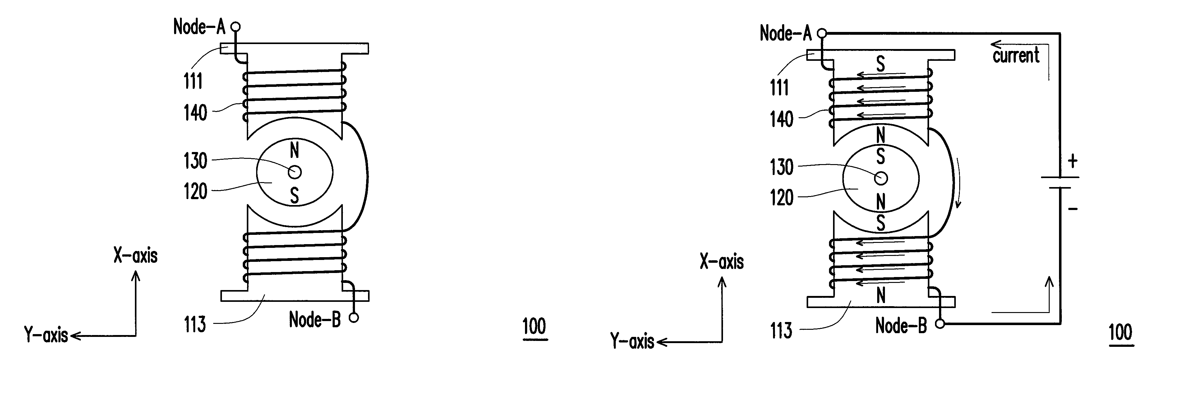
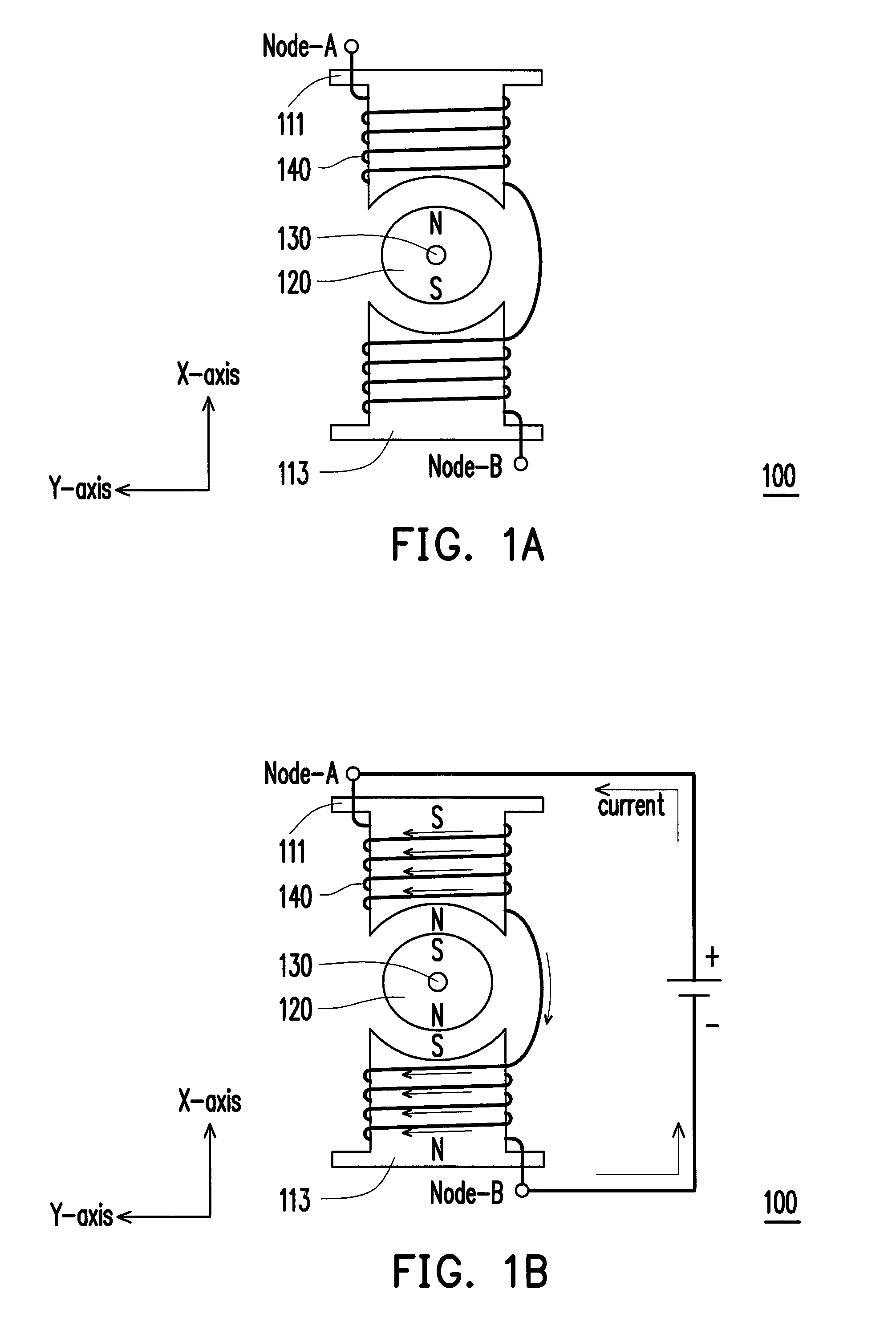
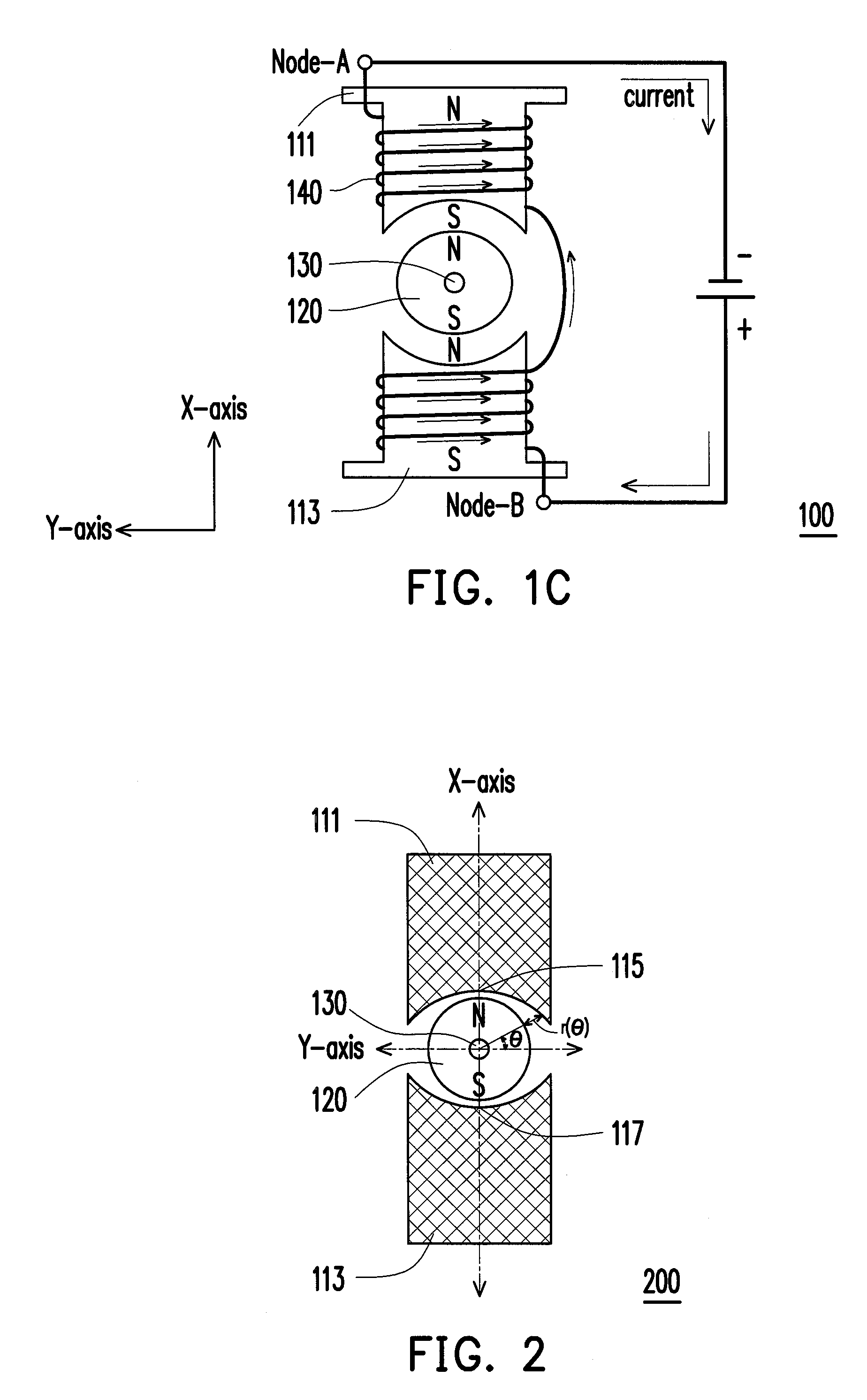
[0041]FIG. 1A, FIG. 1B and FIG. 1C are schematic views of the invention for a bistable latching mechanism 100 in the aspect of X-axis and Y-axis according to an embodiment of the invention. Please refer to FIG. 1A. The bistable latching mechanism 100 includes a first permeability material 111, a second permeability material 113, a cylindrical permanent magnet 120, a rotor shaft 130 and a coil 140.
[0042]The cylindrical permanent magnet 120 covers the rotor shaft 130 as the form of concentric circles, and the cylindrical permanent magnet 120 and the rotor shaft 130 move synchr...
PUM
 Abstract
Description
Claims
Application Information