Apparatus for ascertaining and monitoring fill level of medium in a container

a technology for measuring and monitoring the fill level of mediums, which is applied in the direction of antennas, engine lubrication, liquid/fluent solid measurements, etc., can solve the problems of difficult to manufacture dielectric filling bodies with exactly defined, reserved volume, and ineffective coupling of produced electromagnetic waves into waveguides or horn antennas. , to achieve the effect of increasing the mechanical stability and pressure resistance of the dielectric filling body

Inactive Publication Date: 2013-07-09
EHNDRESS KHAUZER GMBKH KO KG
View PDF14 Cites 11 Cited by
  • Summary
  • Abstract
  • Description
  • Claims
  • Application Information

AI Technical Summary

Benefits of technology

[0011]An object of the invention is, therefore, to provide an apparatus, which has minimal influencing of the produced electromagnetic measuring signals and which, thus, increases the efficiency and accuracy of measurement of the apparatus.
[0018]According to an advantageous form of embodiment of the invention, it is provided, that a gas or a gas mixture is introduced into the reserved volume of the dielectric filling body. In order to check the state of sealing of the hermetically sealed, reserved volume, during the manufacturing process, a special gas, such as e.g. helium, is enclosed in the hermetically sealed, reserved volume of the filling body, and possibly escaping gas is measured with a leakage measuring device or a gas measuring device. Through this test, the state of sealing of the reserved volume can be checked in the case of multi-part embodiment. A further advantage of the introduction of a special gas is that moisture-bearing air is displaced out of the reserved volume by the dried and / or hydrophobic gas, whereby no condensate can form in the case of occurring temperature changes. Furthermore, by the use of special gases in the reserved volume, the wave resistance can be matched.
[0021]An advantageous embodiment of the invention provides, that at least one support element is provided in the reserved volume of the dielectric filling body. For increasing the mechanical stability and the pressure resistance of the dielectric filling body with at least one reserved volume, supporting elements are introduced into the reserved volume for uniformly distributing mechanical forces acting outside on the dielectric filling body. The force spreading by the supporting elements is so embodied, that the shape of the dielectric filling body scarcely changes in the case of mechanical forces acting within a certain limiting range.
[0022]According to an advantageous form of embodiment of the invention, it is provided, that a probe securement element is supplied, which is arranged centered in the dielectric filling body and secured against twisting. The rod / cable element of the waveguide is held by the dielectric filling body. The securement of the rod / cable element is accomplished, for example, via a probe securement element, such as e.g. a hex-screw, introduced form-fittingly in the dielectric filling body, whereby the rod / cable element is exchangeable. Due to the shape-locking introduction of the probe securement element into the dielectric filler body, and of the dielectric filling body in the process connection housing, it is possible to effect a replacement of the rod / cable element by a simple counter-rotational movement of the process connection housing relative to the rod / cable element.
[0023]A very advantageous variant of the invention is that in which a dielectric, gas-sealed and / or hydrophobic coating is applied on the surface of the dielectric filling body. Through the coating of the dielectric filling body with a dielectric, gas-sealed and / or hydrophobic material, it is prevented, that a liquid medium or condensate can move by capillary action into a possible gap between the dielectric filling body and the horn antenna housing or the process connection housing. On the other hand, there should be created thereby, a diffusion barrier for preventing diffusion of the medium through the material of the dielectric filling body into the reserved volumes. A further opportunity is to provide the dielectric filling body in the regions, in which the electromagnetic waves of the measuring signals are conveyed and their radiation characteristic or wave resistance matched, with an electrically conductive coating. Through this conductive coating, medium or condensate penetrated into the gap cannot affect the wave resistance and reflection properties of the electromagnetic waves. This electrically conductive coating must be electrically conductively contacted on the horn antenna housing or the process connection housing.

Problems solved by technology

A disadvantage, however, is that the dielectric material of the dielectric filling body influences the wave resistance of the electromagnetic waves of the high-frequency measuring signal and, thus, also the efficiency of the coupling of the produced electromagnetic waves into the waveguide or into the horn antenna.
In the injection-molding method for synthetic materials, it is very difficult to manufacture a dielectric filling body with an exactly defined, reserved volume.

Method used


Image

  • Apparatus for ascertaining and monitoring fill level of medium in a container
  • Apparatus for ascertaining and monitoring fill level of medium in a container
  • Apparatus for ascertaining and monitoring fill level of medium in a container

Examples


Embodiment Construction

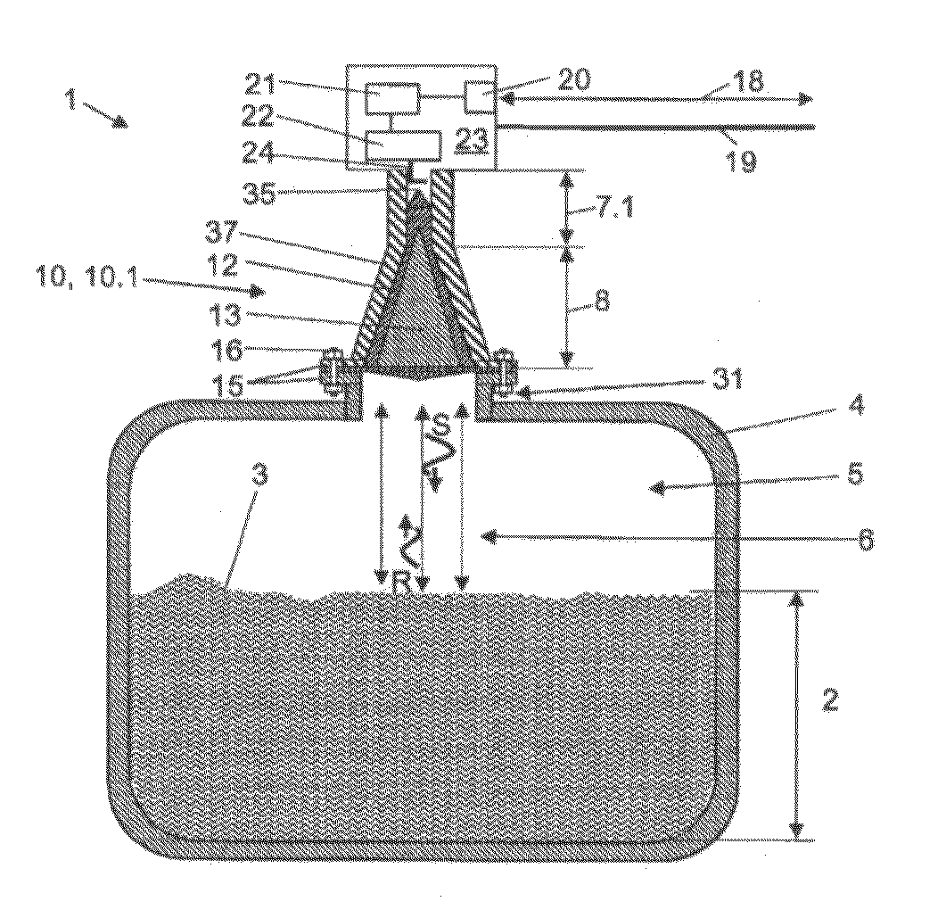
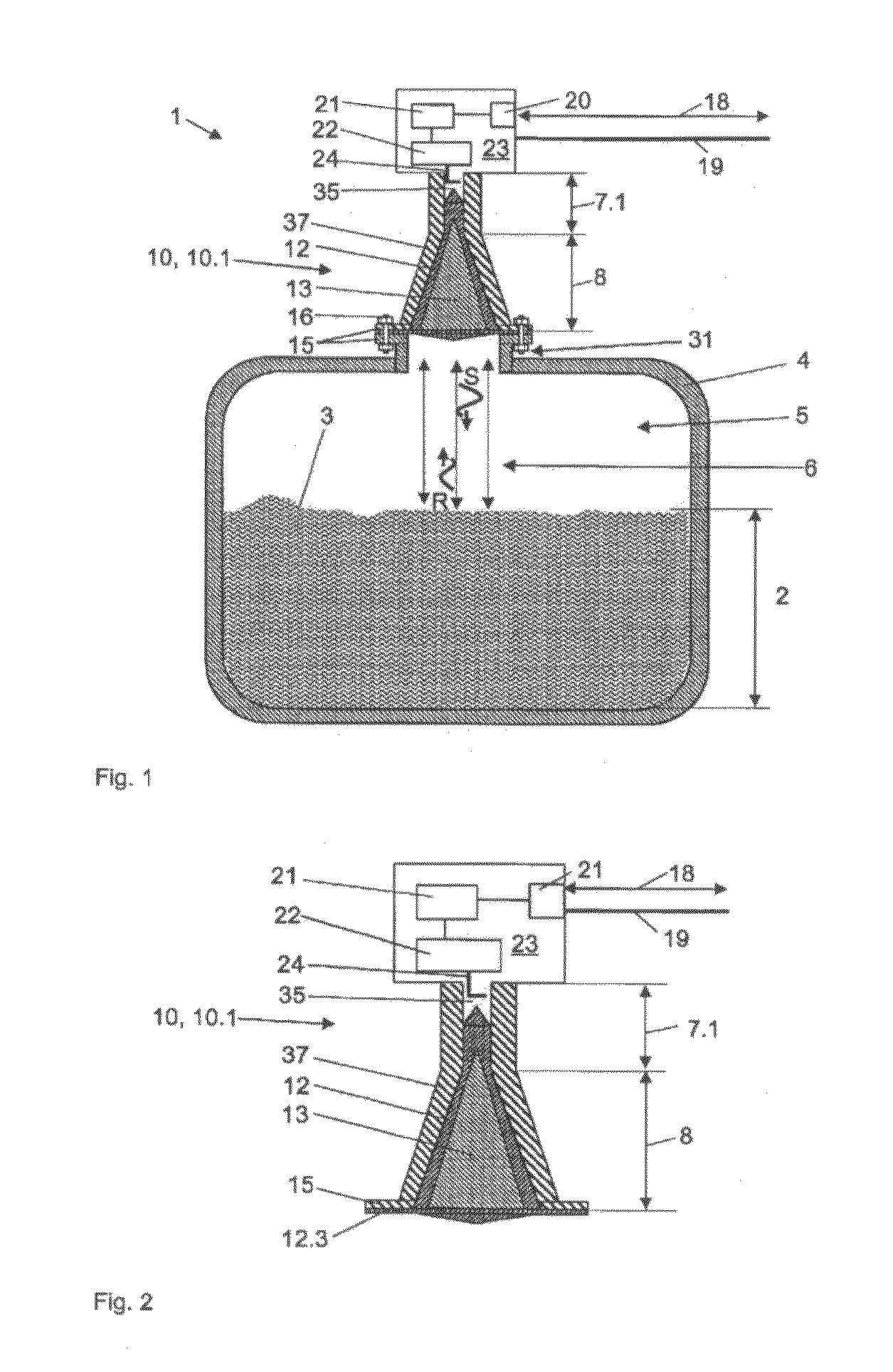
[0036]FIG. 1 shows an example of application of the apparatus 1 of the invention, with an antenna 10, especially a horn antenna 10.1. The apparatus 1, or the measuring device, in FIG. 1 is mounted via securement elements 16 on a flange 15 on a nozzle 31 of the containment 4. The antenna 10 itself can be divided into two basic areas: The coupling region 7 and the antenna region 8.

[0037]The apparatus, or the measuring device, 1 includes a transmitting / receiving unit 22 in the measurement transmitter 23, where the high-frequency measuring signals 6 are produced. Via a coupling element 24, the high-frequency measuring signals 6 are guided into the coupling region 7 or the hollow conductor of the antenna 10 in a certain mode, e.g. TE-mode. The high-frequency measuring signals 6 coupled into the antenna 10 pass through the material of the dielectric filling body 12 and are radiated by the antenna 10 into the process space 5 with a predetermined radiation characteristic as transmission sig...


PUM


Abstract

An apparatus for ascertaining and monitoring fill level of a medium in a container by means of a travel-time measuring method utilizing high-frequency measuring signals. An antenna having an antenna coupling region and an antenna region, or a waveguide having a probe coupling region and a probe measuring region extending into the container is included. Hollow spaces present in the antenna coupling region, in the antenna region, in the probe coupling region and / or in the probe measuring region are filled at least partially with a dielectric filling body. The dielectric filling body has internally at least one, hermetically sealed, reserved volume and the hermetically sealed, reserved volume is so embodied, that the dielectric filling body has a predetermined wave resistance and / or the high-frequency measuring signals have a predetermined propagation characteristic.

Description

TECHNICAL FIELD[0001]The invention relates to an apparatus for ascertaining and monitoring fill level of a medium in a container by means of a travel-time measuring method utilizing high-frequency measuring signals. The apparatus includes an antenna having an antenna coupling region and an antenna region, or a waveguide having a probe coupling region and a probe measuring region extending into the container, wherein hollow spaces present in the antenna coupling region, in the antenna region, in the probe coupling region and / or in the probe measuring region are at least partially filled with a dielectric filling body.BACKGROUND DISCUSSION[0002]Corresponding apparatuses for ascertaining and monitoring fill level in a container are frequently utilized in measuring devices of automation- and process-control-technology. For example, measuring devices are produced and sold by the assignee under the marks Levelflex and Micropilot, which work on the basis of the travel-time measuring method...

Claims


Application Information

Patent Timeline
Patent Type & Authority Patents(United States)
IPC IPC(8): G01R27/04
CPCG01F23/284H01Q19/08
Inventor REIMELT, RALFOSSWALD, DIRK
Owner EHNDRESS KHAUZER GMBKH KO KG
Why Eureka
Try Eureka