Integrated fuel gas characterization system

a fuel gas and characterization system technology, applied in the direction of engine starters, machines/engines, turbine/propulsion engine ignition, etc., can solve the problems of reduced turbine component life, increased emissions of undesirable pollutants, and so as to prolong the life of the turbine component, improve the start-up reliability, and avoid substantial megawatt load swings

Active Publication Date: 2013-07-16
SIEMENS ENERGY INC
View PDF32 Cites 7 Cited by
  • Summary
  • Abstract
  • Description
  • Claims
  • Application Information

AI Technical Summary

Benefits of technology

[0019]Another advantage of the invention is that it provides improved start-up reliability across a wide range of fuel gas compositions and energy content.
[0020]Still another advantage of the invention is that it provides proactive control of the operating parameters and mixing of the different fuel gas compositions to avoid substantial megawatt load swings and maintain safe operating conditions during dynamic fuel events.
[0021]Another advantage of the invention is that it provides extended turbine component life, by reducing or eliminating occurrences of overfiring and megawatt load swings during dynamic fuel events.
[0022]These and other embodiments are described in more detail below.

Problems solved by technology

Where the fuel gas energy content variations do not require shut down of the gas-fired turbine, the change in fuel gas energy content results in substantial megawatt load swings, engine overfiring, and increased emissions of undesirable pollutants, such as NOX and CO.
Thus, while turbine component manufacturers design turbine components to handle the extreme firing temperatures and loads experienced during design conditions, turbine component life can be reduced due to extreme temperatures or forced caused by overfiring, megawatt load swings, or both.
However, by the time the adjustment is made, the gas turbine engine has already experienced a megawatt load swing, which can damage turbine engine components These prior art systems also often fail to address operational issues including, but not limited to, increased combustor dynamics, increased flashback potential and reduced start-up reliability.

Method used


Image

  • Integrated fuel gas characterization system
  • Integrated fuel gas characterization system
  • Integrated fuel gas characterization system

Examples


Embodiment Construction

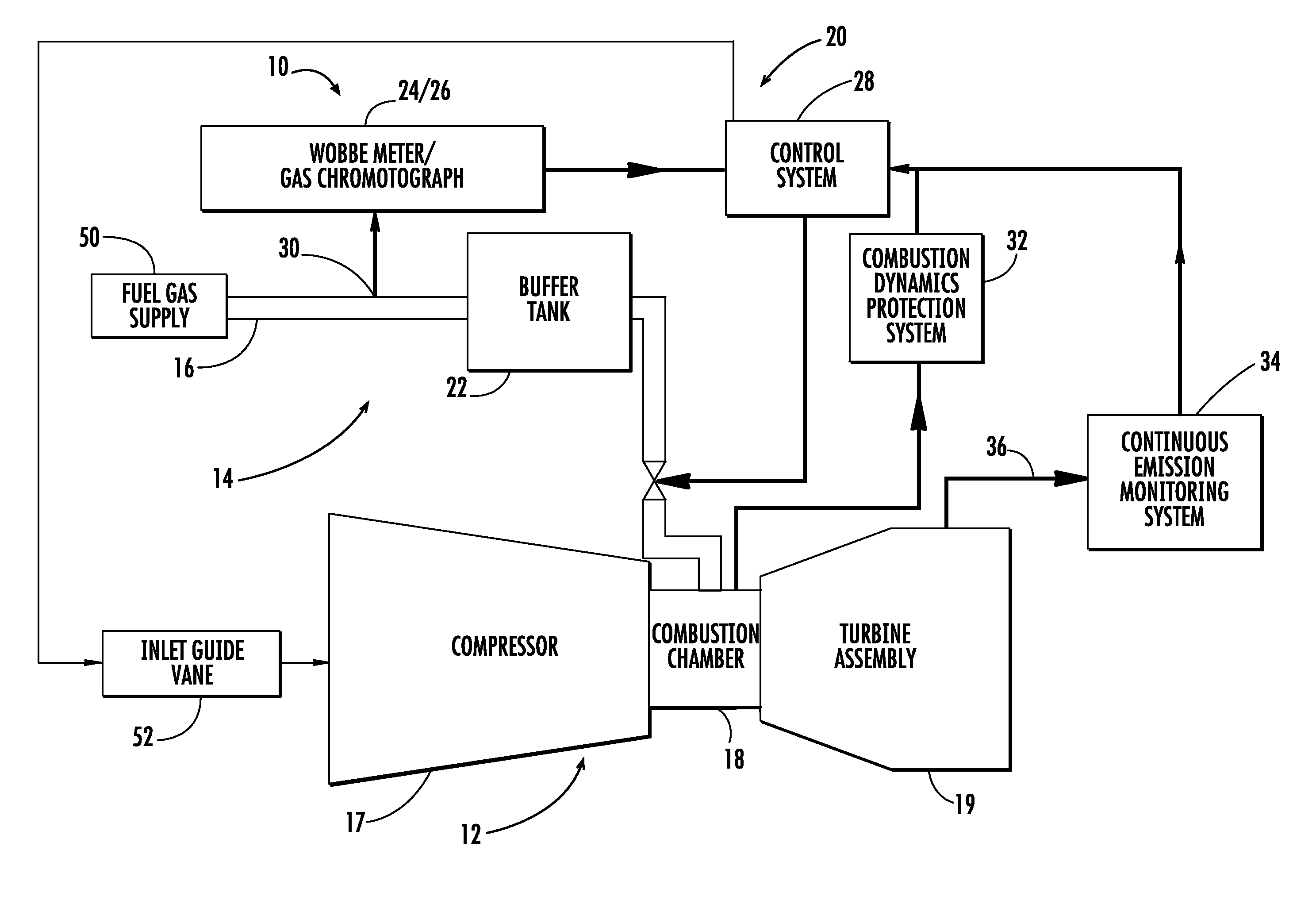
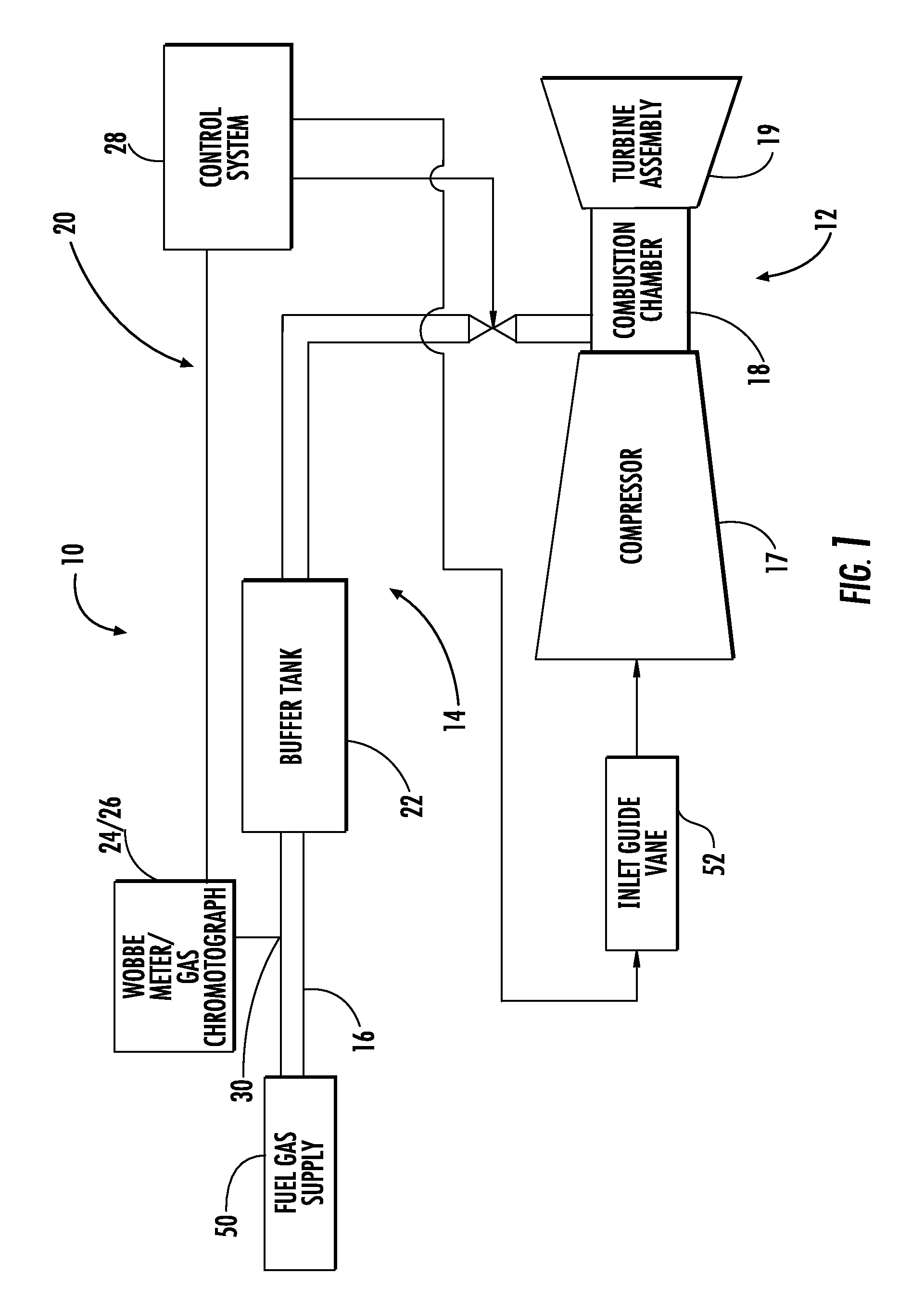
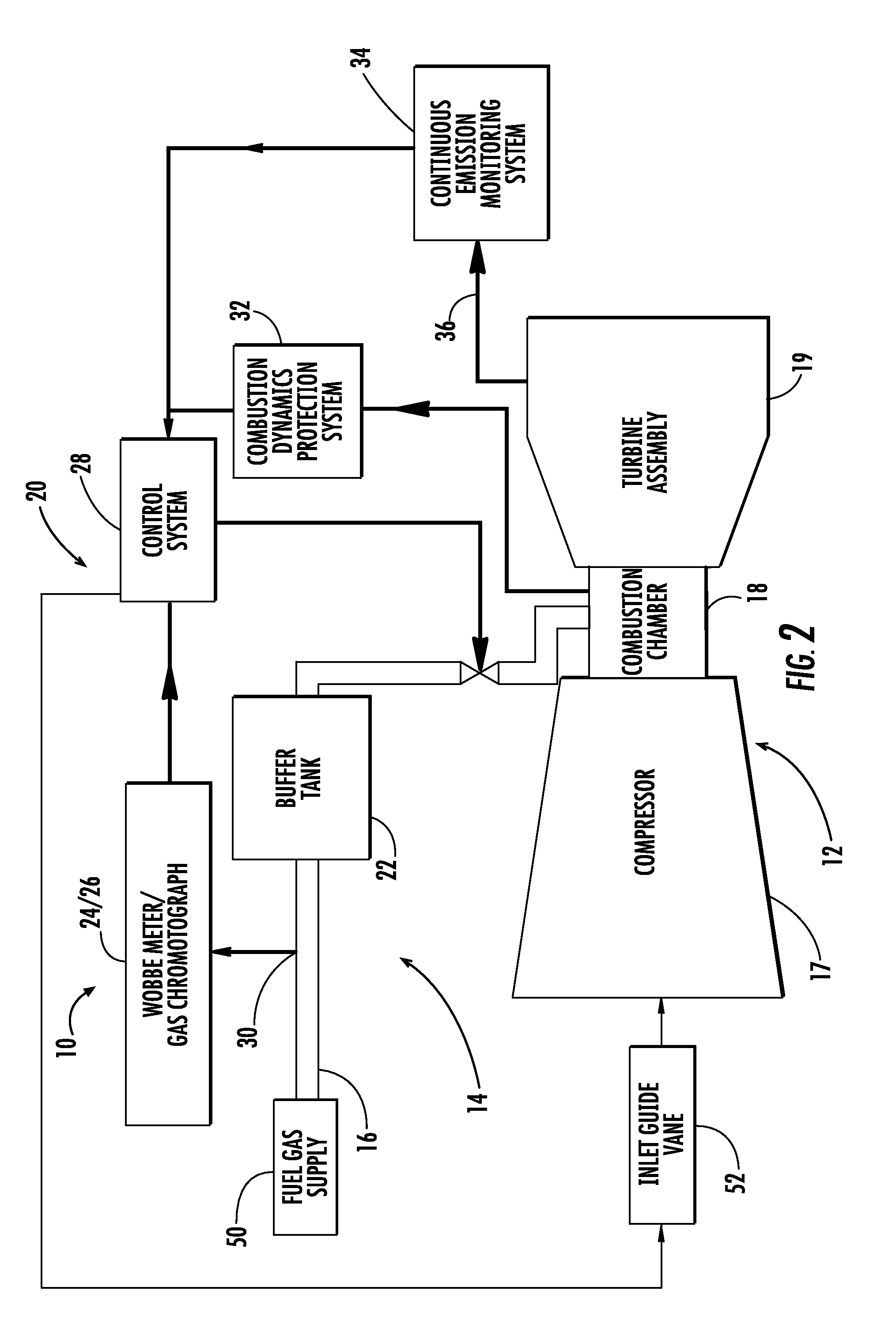
[0026]As shown in FIGS. 1-2, the invention is directed to a gas turbine engine 10 that includes an integrated fuel gas characterization system 20 having a buffer tank 22 and a control system 28. The control system 28 of the integrated fuel gas characterization system 20 is a proactive, or feed forward, system that adjusts operating parameters of the gas turbine engine 10 based on the rate of change of fuel gas 16 properties. The operating parameters can be adjusted at or before the time when the changes to the fuel gas 16 composition reach the combustion chamber 18. The control system 28 may also be configured to determine heating value changes in the fuel gas and adjust the air flow to the compressor 17 or fuel gas flow to the combustor 18, or both, to maintain a design fuel-to-air ratio. By sensing heating value changes of the fuel gas and adjusting the air or fuel gas flow, the control system 28 enables the gas turbine engine 10 to operate more efficiently by taking advantage of ...


PUM


Abstract

A gas turbine engine that includes a compressor, a combustion stage, a turbine assembly, a fuel gas feed system for supplying fuel gas to a combustion stage of the gas turbine, an integrated fuel gas characterization system, and a buffer tank is disclosed. The integrated fuel gas characterization system may determine the heating value of the fuel and adjust either the airflow to the compressor or the fuel gas flow to the combustor to maintain a design fuel-to-air ratio.

Description

FIELD OF THE INVENTION[0001]The invention is directed generally to a fuel gas characterization system for operating a gas turbine engine, and more particularly to a system for proactively adjusting operating parameters of the gas turbine engine due to changes in fuel gas composition.BACKGROUND OF THE INVENTION[0002]Much of the power generation capacity in North America is provided by gas-fired turbines. These gas-fired turbines are general optimized to operate using fuel gas with a constant energy content. Significant variations in fuel gas energy content can result in the need for an extended shut down of the gas-fired turbine while the turbine control systems are adjusted to operate using the new fuel gas. Variations in fuel gas energy content is becoming more commonplace with greater imports of liquid natural gas (LNG).[0003]Where the fuel gas energy content variations do not require shut down of the gas-fired turbine, the change in fuel gas energy content results in substantial ...

Claims


Application Information

Patent Timeline
Patent Type & Authority Patents(United States)
IPC IPC(8): F02C7/22F02C9/00
CPCF02C9/40
Inventor NAG, PRATYUSH
Owner SIEMENS ENERGY INC
Why Eureka
Try Eureka