
Sealed end t-nut

a t-nut and sealing technology, applied in the direction of threaded fasteners, manufacturing tools, bolts, etc., can solve the problems of lack of strength of zinc alloys, high cost of brass inserts, and high cost of zinc die cast inserts

Active Publication Date: 2013-07-16
STAFAST PROD
View PDF161 Cites 19 Cited by
  • Summary
  • Abstract
  • Description
  • Claims
  • Application Information

AI Technical Summary

Benefits of technology

The invention relates to a fastener made of steel or stainless steel that includes a t-nut and an end cap. The fastener is designed to be strong and durable, with a barrel that is fully threaded and sealed to the flange, preventing dirt, water, and moisture from entering. The invention provides a cost-effective and efficient manufacturing process that allows for a wide variety of thread sizes, barrel lengths, and flange diameters. The configuration of the sealed end T-Nut allows for easy customization for different applications, such as plastic molding, snowboards, and adhesive spraying.

Problems solved by technology

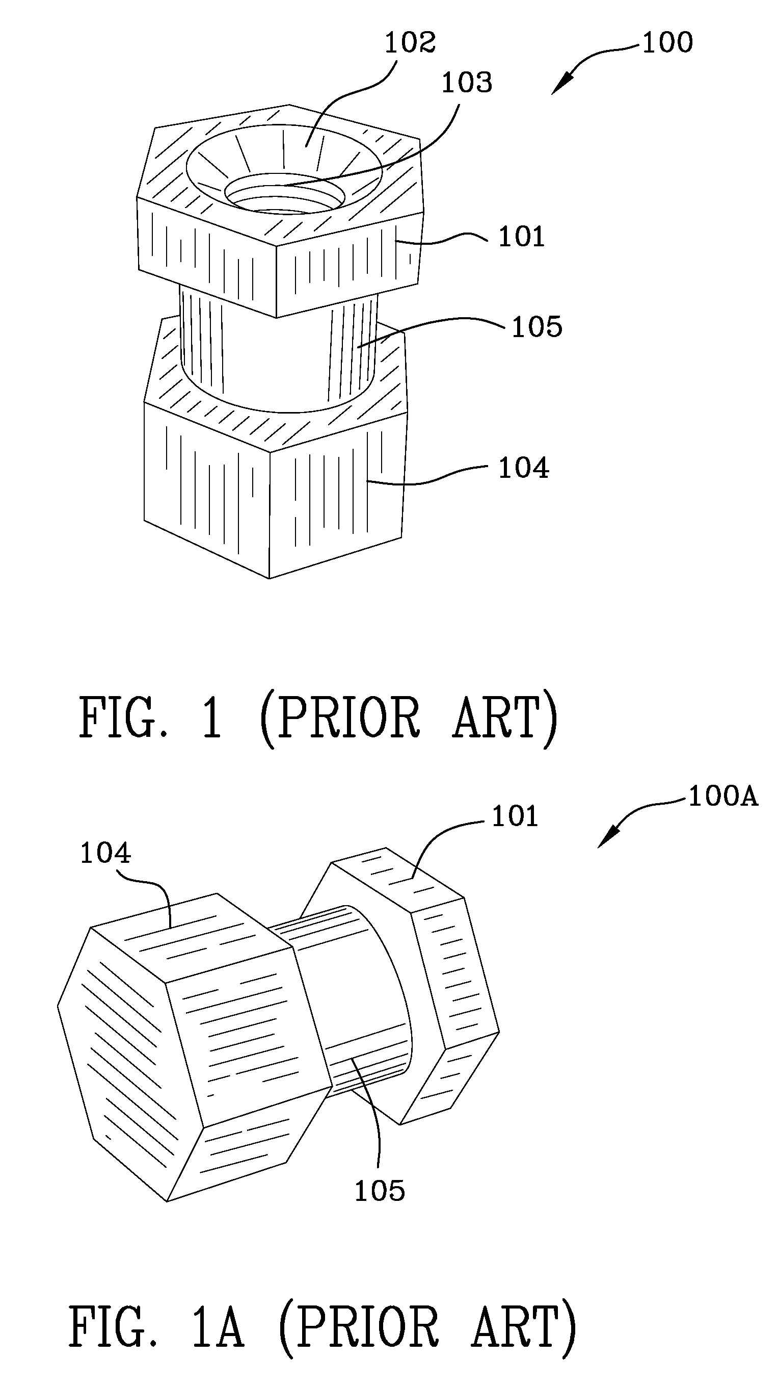
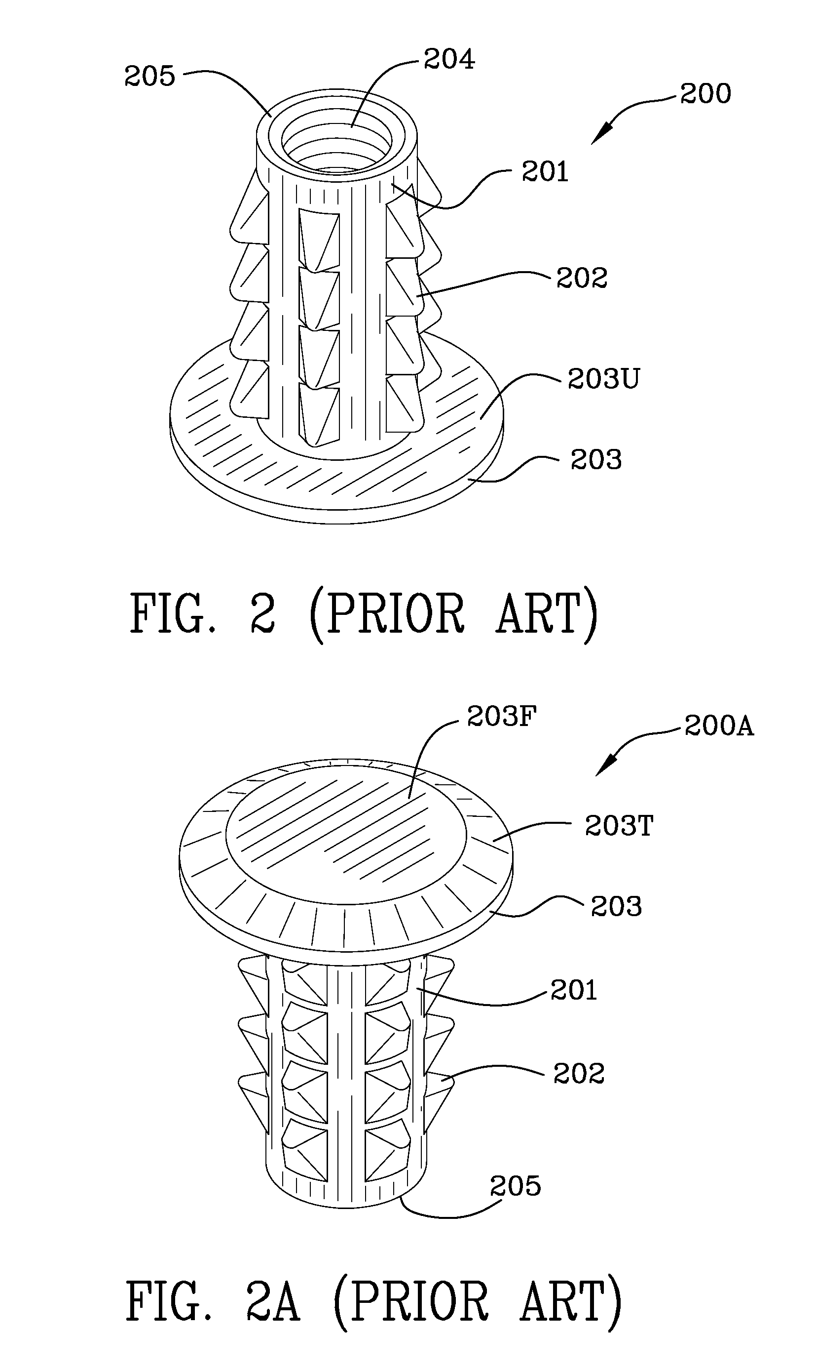
A drawback with brass inserts is high cost due to manufacturing time and material costs.
Zinc die cast inserts are cost prohibitive due to the cost of the molds.
Further, there is considerable difficulty in plating zinc and zinc alloys to provide good corrosion resistance and lack of strength of the zinc alloys.
Issues with cold headed steel parts include the cost to manufacture and limitations on shapes that this manufacturing process can generate to fit different applications.
All three of these manufacturing methods have one other serious drawback.
The amount of thread that can be tapped in a blind hole is limited.

Method used


Image

  • Sealed end t-nut
  • Sealed end t-nut
  • Sealed end t-nut

Examples


Embodiment Construction

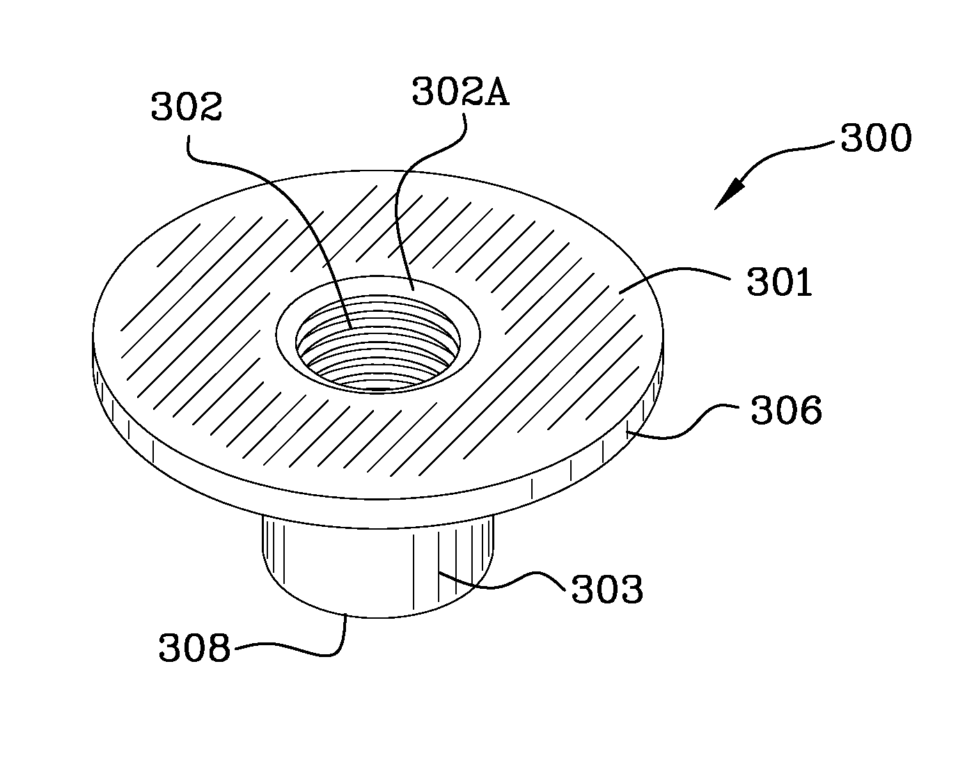
[0050]FIG. 3 is a top perspective view 300 of a t-nut threaded completely through the part. FIG. 3A is another perspective view 300A of the t-nut threaded 302 completely through the part. FIG. 3B is a top view 300B of the t-nut with through threads. Flange 301 of the t-nut is viewed in both FIGS. 3 and 3A and is generally cylindrically shaped and terminates in a circumferential edge portion 306. T-nuts are manufactured from sheets or slugs of steel (or stainless steel) which is deformed to include a barrel or shank such as that denoted by reference numeral 303. Barrel or shank 303 terminates in an open end portion 308. Shank 303 is cylindrically shaped and includes interior threads 302. Interior threads 302 extend all the way from the opening 302A in the flange to the end portion 308 of the shank 303. Shank 303 transitions in a curved surface 304 into the underside 305 of the flange. FIG. 3C is a side view 300C of the t-nut with through threads. FIG. 3D is a cross-sectional view 300...


PUM

PropertyMeasurementUnit
resistanceaaaaaaaaaa
shapeaaaaaaaaaa
timeaaaaaaaaaa

Abstract

A fastener includes a t-nut having a barrel and a flange. The flange includes an opening which leads to a threaded barrel. The threaded barrel extends from the opening in the flange to a distal end portion thereof. An end cap has an annular recess on a first side thereof and has a raised annular ridge on a second side thereof. The raised annular ridge of the end cap is affixed to the flange of the t-nut by welding the end cap to the flange. Dirt, water and moisture cannot enter the barrel because the end cap is sealed to the flange. Additionally, the barrel may be relatively short as it is fully threaded prior to the affixation of the end cap to the flange.

Description

[0001]This application claims priority to U.S. provisional patent application Ser. No. 61 / 089,859 filed Aug. 18, 2008.FIELD OF THE INVENTION[0002]The invention is the field of closed-end fasteners.BACKGROUND OF THE INVENTION[0003]Presently in the field there are several different ways that closed end fasteners are used and are manufactured.[0004]Typical applications are molding applications where the closed end is used to prevent plastic from flowing into the back side of a fastener which would fill and render the threads on the fastener un-usable. Closed end fasteners are also used in tank (fluid container) type applications to prevent fluid from escaping the tank yet provide an external attachment point for the tank. Finally, closed end fasteners are commonly used in snow board applications where the closed end is used to prevent epoxy resins from flowing into the part and filling the threads with plastics.[0005]Presently the market place use different types of closed end fastener...

Claims


Application Information

Patent Timeline
Patent Type & Authority Patents(United States)
IPC IPC(8): B21G5/00B21D53/24B21K1/64F16B37/04A47G3/00
CPCB23K11/14F16B33/004F16B37/00F16B2037/007
Inventor SELLE, STEPHEN
Owner STAFAST PROD
Learn More