Driving power control circuit for light emitting diode and method thereof

a technology of driving power control circuit and light emitting diode, which is applied in the direction of instruments, light sources, electroluminescent light sources, etc., can solve the problems of overheating and instability of the whole power driving circuit, and the inability of different led strings to effectively maintain their brightness consistency, etc., to achieve the effect of improving circuit reliability

Active Publication Date: 2013-07-16
AU OPTRONICS CORP
View PDF18 Cites 3 Cited by
  • Summary
  • Abstract
  • Description
  • Claims
  • Application Information

AI Technical Summary

Benefits of technology

[0006]Accordingly, the present invention is directed to a driving power control circuit adapted to drive power supplies of a plurality of LED strings, in order to improve reliability of circuit and overcome heat loss problems generated by electronic components of the whole power driving circuit associated with the prior art.
[0015]In the method of the invention to solving the problems associated with the prior art, a plurality of switch units are set at the ends of the plurality of LED strings. A control unit is set in the driving power control circuit, in order to drive the plurality of the LED strings to emit light and obtain node voltages. And the adjusting module set in the control unit can eliminate ripple of node voltages to get the feedback voltages, and can proceed with control operation in the characteristic curve of driving currents to node voltages according to the feedback voltages. Therefore, the invention of the driving power control circuit not only improve reliability of the circuit, but also can overcome heat loss problems of the electronic components caused by voltage differences.

Problems solved by technology

But each LED string has different load characteristics; this results in that different LED strings cannot be effectively maintained to have their brightness in consistency.
Moreover, too high temperature of the power driving circuits may be caused by power loss of electronic components in the power driving circuits.
But using this method, ripple distortion problems may exist in power supply outputted by the power driving circuit, resulting in overheating and instability of the whole power driving circuit.

Method used


Image

  • Driving power control circuit for light emitting diode and method thereof
  • Driving power control circuit for light emitting diode and method thereof
  • Driving power control circuit for light emitting diode and method thereof

Examples


Embodiment Construction

[0024]In the following detailed description of the preferred embodiments, reference is made to the accompanying drawings which form a part hereof, and in which are shown by way of illustration specific embodiments in which the invention may be practiced. It is to be understood that other embodiment may be utilized and structural changes may be made without departing from the scope of the present invention. Also, it is to be understood that the phraseology and terminology used herein are for the purpose of description and should not be regarded as limiting. The use of “including,”“comprising,” or “having” and variations thereof herein is meant to encompass the items listed thereafter and equivalents thereof as well as additional items. Accordingly, the descriptions will be regarded as illustrative in nature and not as restrictive.

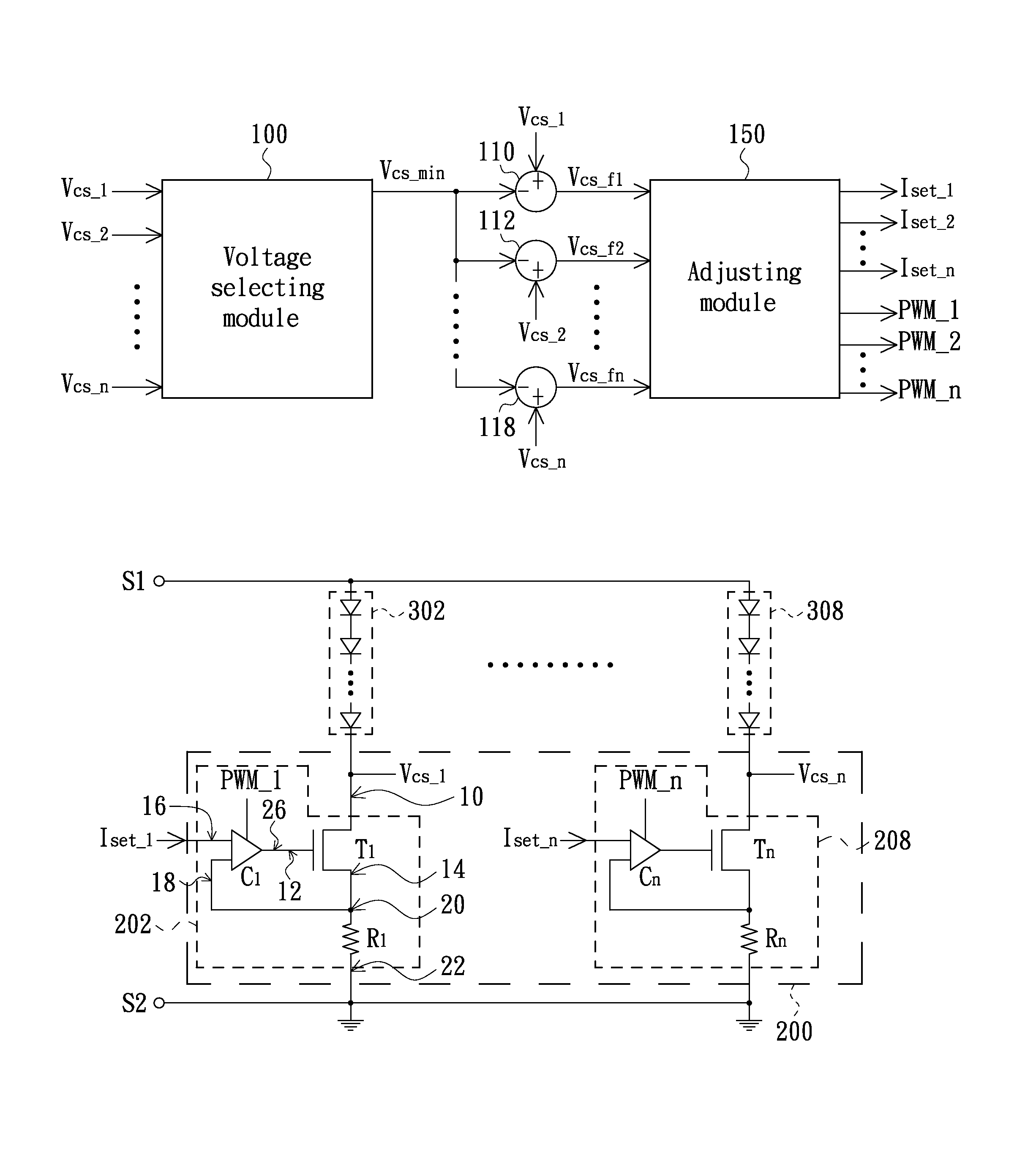
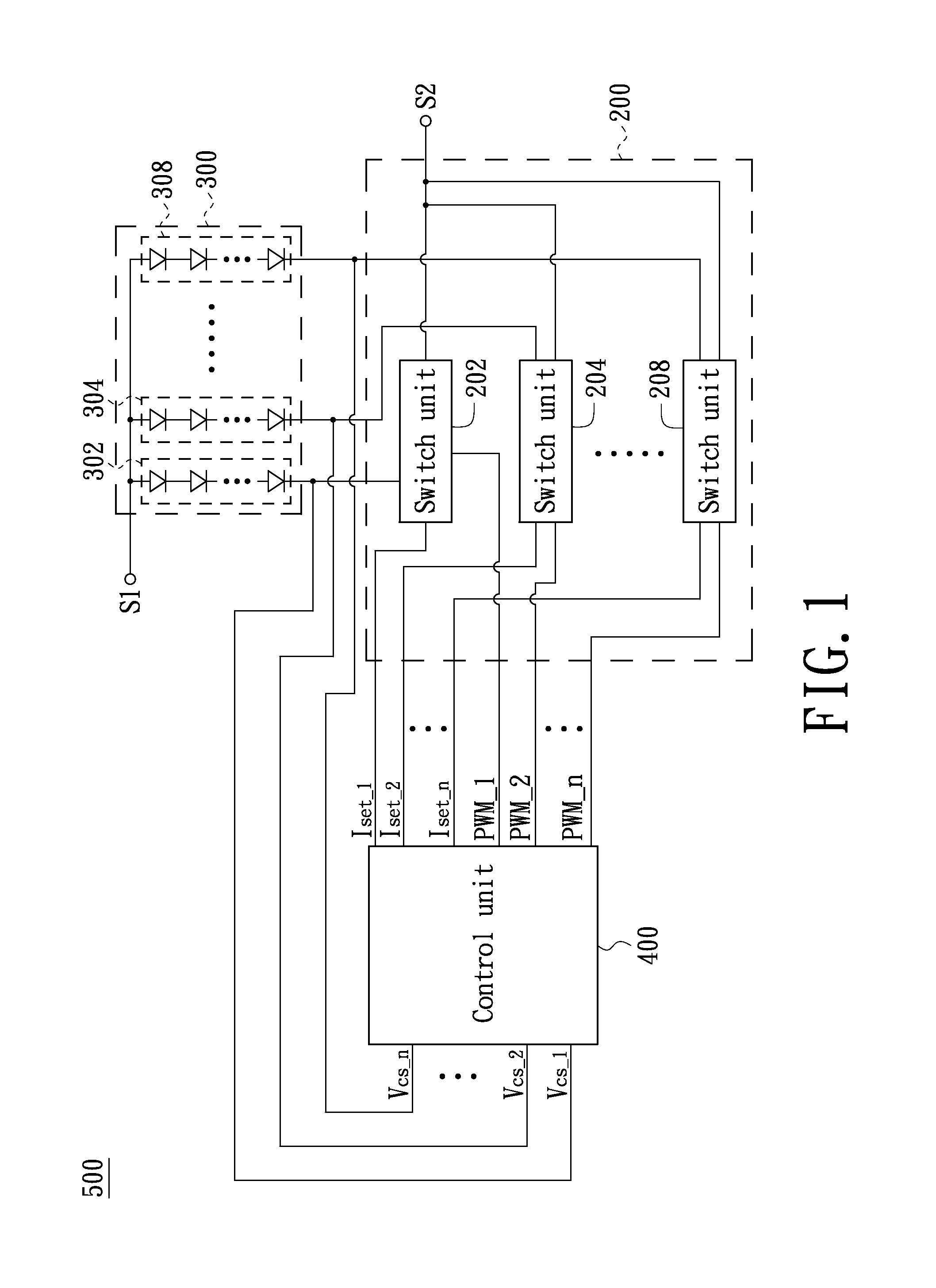
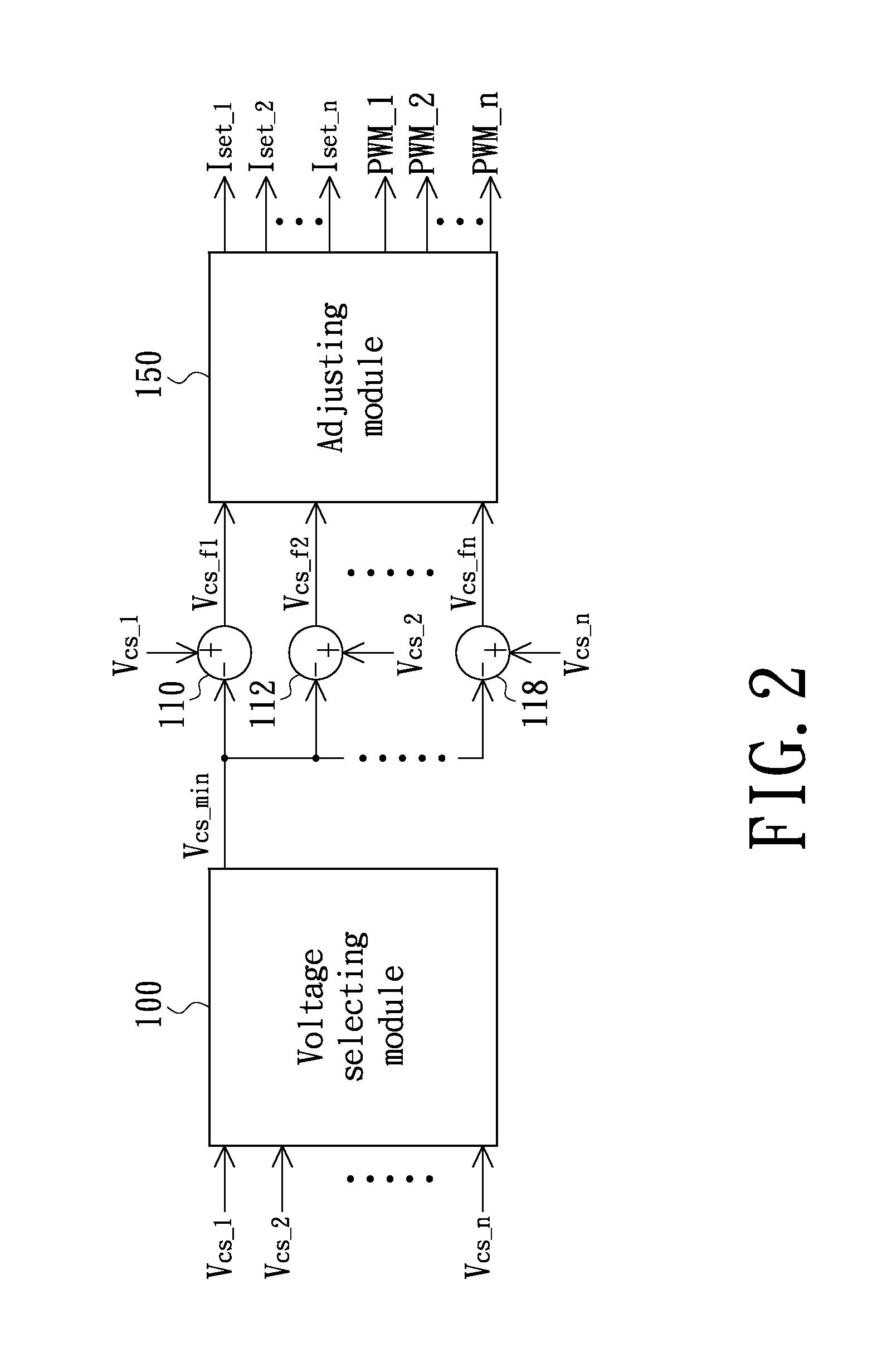
[0025]Referring to FIG. 1, showing a partial circuit diagram of a driving power control circuit for LEDs in accordance with an exemplary embodiment of the p...


PUM


Abstract

A driving power control circuit and method for light emitting diodes (LEDs) are provided. The driving power control circuit includes a plurality of switch units and a control unit. Each switch unit is electrically coupled to one LED string whose end generates node voltage. The control unit includes a voltage selecting module, a subtractor, and an adjusting module. The voltage selecting module is electrically coupled to the node voltages and outputs one of the node voltages as a reference node voltage. The subtractor is electrically coupled to an output terminal of the voltage selecting module and generates a corresponding feedback voltage according to the reference node voltage and the node voltage. The adjusting module is electrically coupled to an output terminal of the subtractor and outputs a corresponding adjusting signal according to the feedback voltage to determine whether the corresponding switch unit is turned on.

Description

BACKGROUND[0001]1. Technical Field[0002]The present invention generally relates to a driving power control circuit and a method thereof and, particularly to a driving power control circuit or light emitting diode (LED) and method thereof.[0003]2. Description of the Related Art[0004]LEDs are as new generation lighting components, they have the advantages of saving electricity and long useful life, and therefore they are widely used in various devices, especially used in backlight modules of flat-panel displays (e.g., liquid crystal displays). LED strings of the backlight modules can emit light through LEDs thereof driven by power driving circuits. But each LED string has different load characteristics; this results in that different LED strings cannot be effectively maintained to have their brightness in consistency. Moreover, too high temperature of the power driving circuits may be caused by power loss of electronic components in the power driving circuits.[0005]Therefore, during t...

Claims


Application Information

Patent Timeline
Patent Type & Authority Patents(United States)
IPC IPC(8): H05B37/00H05B39/00H05B41/00
CPCH05B33/0827H05B45/46
Inventor LI, YUEH-HANHSU, SHENG-KAI
Owner AU OPTRONICS CORP
Why Eureka
Try Eureka