Dielectric ceramic and laminated ceramic capacitor

a technology of laminated ceramic and dielectric ceramic, which is applied in the direction of fixed capacitors, rare earth metal compounds, inorganic chemistry, etc., can solve the problems of insufficient reliability and especially life characteristics in load tests, and achieve the effect of high reliability

Inactive Publication Date: 2013-07-16
MURATA MFG CO LTD
View PDF10 Cites 4 Cited by
  • Summary
  • Abstract
  • Description
  • Claims
  • Application Information

AI Technical Summary

Benefits of technology

[0008]Accordingly, it is an object of the present invention is to provide a dielectric ceramic capable of realizing high reliability even when the thickness of a dielectric ceramic layer is further reduced and a laminated ceramic capacitor constituted using the dielectric ceramic.
[0015]According to the dielectric ceramic according to preferred embodiments of the invention, a reduction in the oxygen vacancy concentration or the movement of oxygen vacancies can be suppressed without reducing the insulation properties in the main component particles by uniformly forming a solid solution of each of R and B in as the main component particles while maintaining the charge balance.
[0016]Therefore, when a laminated ceramic capacitor is constituted using the dielectric ceramic according to preferred embodiments of the invention, high reliability and particularly favorable life characteristics in a load test can be realized even when the thickness of the dielectric ceramic layer is reduced.
[0017]In the dielectric ceramic according to preferred embodiments of the invention, when the R content is selected to be about 0.01 to about 2% by mol in the entire (Ba, R) or (Ba, Ca, R) site, more favorable life characteristics can be achieved.
[0018]When the V content is selected to be about 0.01 to about 1% by mol in the entire (Ti, V) site, more favorable life characteristics can be achieved.
[0019]When the Ca content is selected to be about 0.01 to about 15% by mol in the entire (Ba, Ca, R) site, more favorable life characteristics can be achieved.

Problems solved by technology

However, even when the dielectric ceramic described in Patent Document 1 is used, the reliability and particularly the life characteristics in a load test are insufficient when there is a further reduction in the thickness of the dielectric ceramic layer, and thus a further improvement has been demanded.

Method used


Image

  • Dielectric ceramic and laminated ceramic capacitor
  • Dielectric ceramic and laminated ceramic capacitor

Examples


example 1

[0035]In Example 1, the case where the main component contains (Ba, R)(Ti, V)O3 and the case where the main component contains (Ba, R)TiO3 and Ba(Ti, V)O3 were compared.

(A) Production of Ceramic Materials

[0036]First, powders of Dy2O3, V2O5, BaCO3, TiO2, and R2O3 were prepared as a starting material of the main component. Then, each powder was weighed so that the composition in the main component particles was (Ba0.99Dy0.01)TiO3 in sample 101, Ba(Ti0.995V0.005)O3 in sample 102, and (Ba0.99Dy0.01)(Ti0.995V0.005)O3 in sample 103, as shown in the column of “Composition in main component particles” of Table 1, and then the powders were mixed for about 8 hours in a ball mill using water as a medium. Thereafter, the mixture was evaporated and dried, and then fired at about 1100° C. for about 2 hours, thereby obtaining a main component powder of each of the samples 101 to 103.

[0037]Next, powders of MnCO3 and SiO2 as accessory components were prepared. The powders of MnCO3 and SiO2 each were...

example 2

[0048]In Example 2, a dielectric ceramic was evaluated in which the main component was (Ba, R)(Ti, V)O3, similar to sample 103 of Example 1 but the amount of V and the amount of R were changed.

(A) Production of Ceramic Raw Materials

[0049]A dielectric ceramic raw material powder was obtained in the same manner as in Example 1, except that the composition of the main component powder was (Ba1-x / 100Dyx / 100)(Ti1-y / 100Vy / 100)O3 using Dy as R, and the content “x” of Dy as R in the (Ba, R) site and the content “y” of V in the (Ti, V) site were adjusted to have values shown in the column of “x” and “y” of Table 2, respectively.

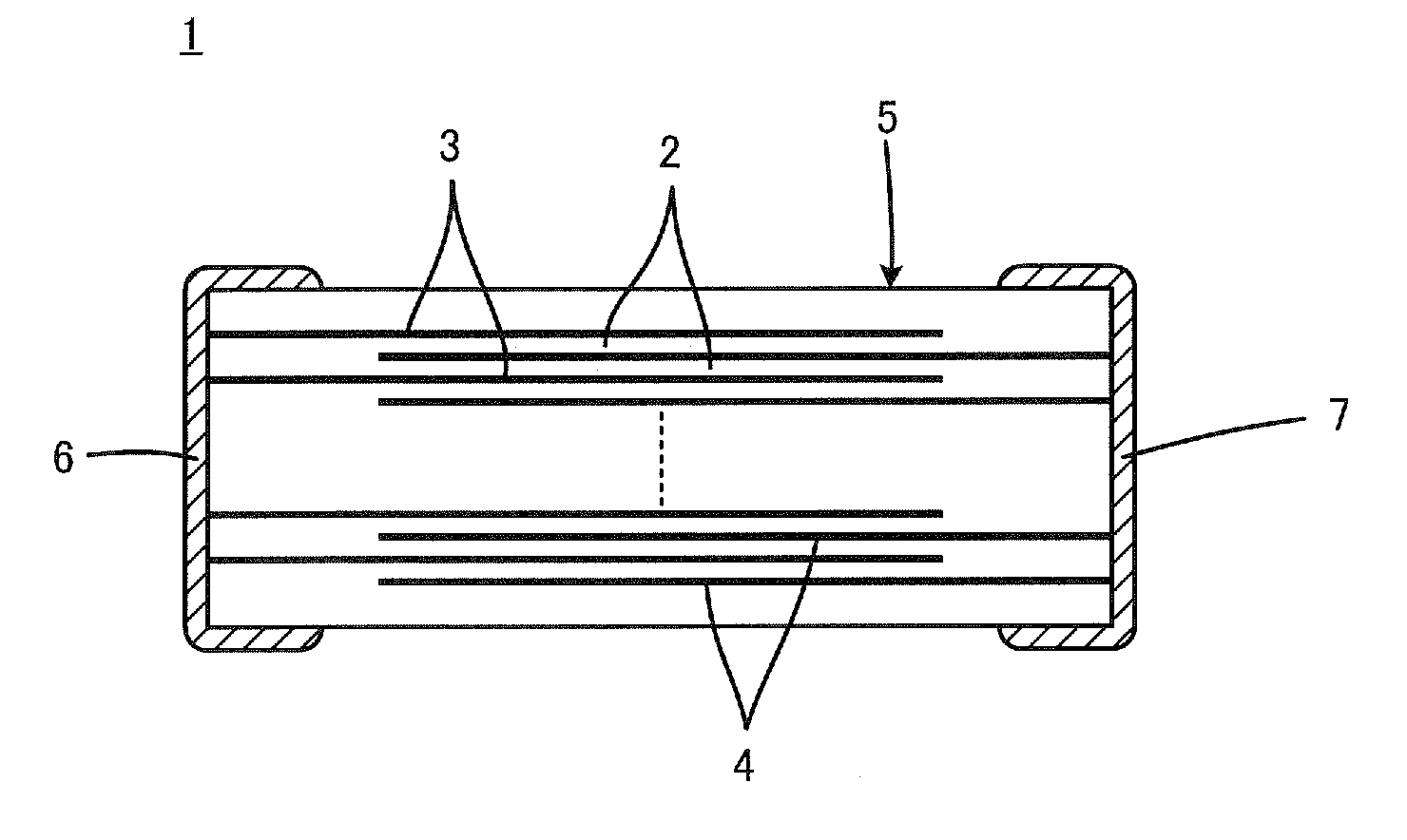
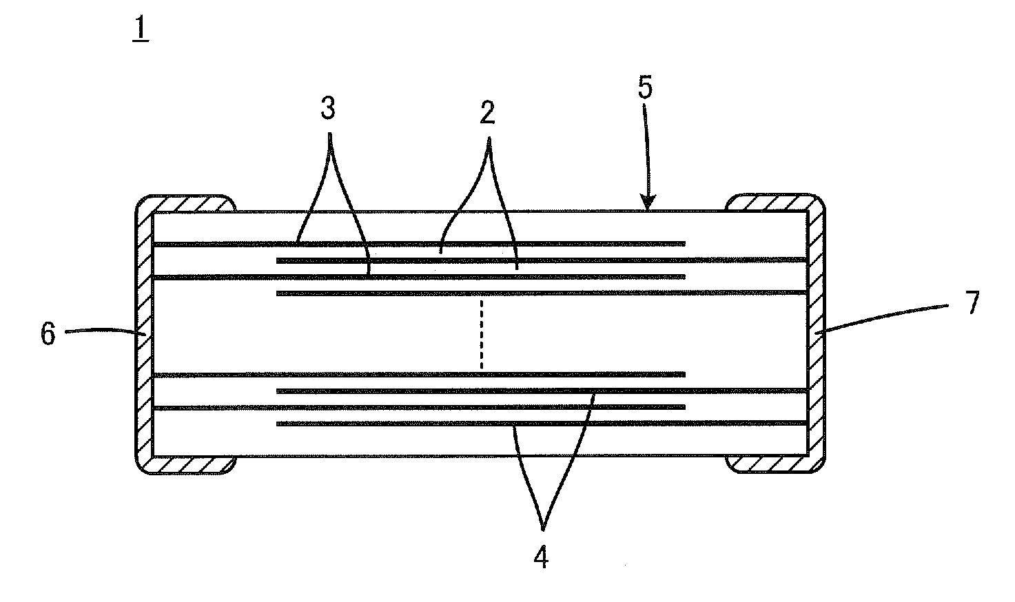
(B) Production of Laminated Ceramic Capacitor

[0050]A laminated ceramic capacitor of each sample was produced using the dielectric ceramic raw material powder in the same manner as in Example 1.

(C) Evaluation of Properties

[0051]A high temperature load life test was carried out in the same manner as in Example 1. The results are shown in the column of a “Number of defec...

example 3

[0058]In Example 3, laminated ceramic capacitors of each sample were produced in the same manner as in Example 1, replacing Dy as R with the elements shown in the column of the “R species” of Table 3 in the composition in the main component particles of the sample 103 in Example 1, and a high temperature load life test was similarly carried out. In Example 3, the number of defects was determined for samples in which the insulation resistance value was about 100 kΩ or lower when not only at about 1000 hours but also when about 2000 hours passed in the high temperature load life test.

[0059]

TABLE 3Number of defects in hightemperature load life testSample No.R species1000 hours2000 hours301La0 / 1000 / 100302Gd0 / 1000 / 100303Eu0 / 1000 / 100304Ho0 / 1000 / 100305Er0 / 1000 / 100306Yb0 / 1000 / 100307Y0 / 1000 / 100

[0060]As shown in Table 3, all of samples 301 to 307 exhibited excellent reliability.


PUM

PropertyMeasurementUnit
temperatureaaaaaaaaaa

Abstract

A dielectric ceramic capacitor that has excellent reliability and particularly excellent life characteristics in a load test even when the thickness of a dielectric ceramic layer is reduced uses a dielectric ceramic as a dielectric ceramic layer in a laminated ceramic capacitor which is a substance containing, as the main component, (Ba, R)(Ti, V)O3 or (Ba, Ca, R)(Ti, V)O3 in which R is at least one selected from La, Ce, Pr, Nd, Sm, Eu, Gd, Tb, Dy, Ho, Er, Tm, Yb, Lu, and Y, and in which both V and R are present uniformly in the main component particles.

Description

BACKGROUND OF THE INVENTION[0001]1. Field of the Invention[0002]The present invention relates to a dielectric ceramic and a laminated ceramic capacitor, and particularly relates to a dielectric ceramic suitable for use in a thin layer, large capacity, laminated ceramic capacitor and a laminated ceramic capacitor constituted using the dielectric ceramic.[0003]2. Description of the Related Art[0004]Mentioned as one of effective measures for satisfying demands for a reduction in the size and an increase in the capacity of a laminated ceramic capacitor is to reduce the thickness of the dielectric ceramic layers provided in the laminated ceramic capacitor. However, the electric field strength per layer of the dielectric ceramic layer becomes higher with the reduction in the thickness of the dielectric ceramic layer. Therefore, the dielectric ceramic used has been required to have more reliability, and particularly higher life characteristics in a load test.[0005]As the dielectric ceramic...

Claims


Application Information

Patent Timeline
Patent Type & Authority Patents(United States)
IPC IPC(8): H01G4/06C04B35/00
CPCC04B35/4682C04B35/62685H01G4/30H01G4/1227C04B2235/3208C04B2235/3224C04B2235/3225C04B2235/3229C04B2235/3239C04B2235/3262C04B2235/3418C04B2235/3227H01G4/12C04B35/46
Inventor YAO, TAKAYUKI
Owner MURATA MFG CO LTD
Why Eureka
Try Eureka