Hybrid system control apparatus and hybrid system control method

a hybrid system and control apparatus technology, applied in the direction of machine/engine, process and machine control, vehicle sub-unit features, etc., can solve the problems of deteriorating fuel economy, achieve the effect of improving fuel economy, reducing the heat capacity of air, and reducing the temperature of the catalys

Active Publication Date: 2013-07-23
TOYOTA JIDOSHA KK
View PDF16 Cites 16 Cited by
  • Summary
  • Abstract
  • Description
  • Claims
  • Application Information

AI Technical Summary

Benefits of technology

[0013]As described above, during cold start of the hybrid system, the viscosity of lubricant that lubricates the driving elements forming the electric motor system is sometimes very high. Therefore, when the vehicle is driven by the power output by the electric motor, increase of friction loss may deteriorate fuel economy in cold start.
[0024]As described above, the target boost pressure is set finely in accordance with the vehicle speed of the hybrid vehicle, the ambient air temperature, and the temperature of the electric motor system cooling medium, and thus the engine load can be controlled accurately. Therefore, the warm-up of the electric motor system can be preformed efficiently.

Problems solved by technology

Therefore, when the vehicle is driven by the power output by the electric motor, increase of friction loss may deteriorate fuel economy in cold start.

Method used


Image

  • Hybrid system control apparatus and hybrid system control method
  • Hybrid system control apparatus and hybrid system control method
  • Hybrid system control apparatus and hybrid system control method

Examples


first embodiment

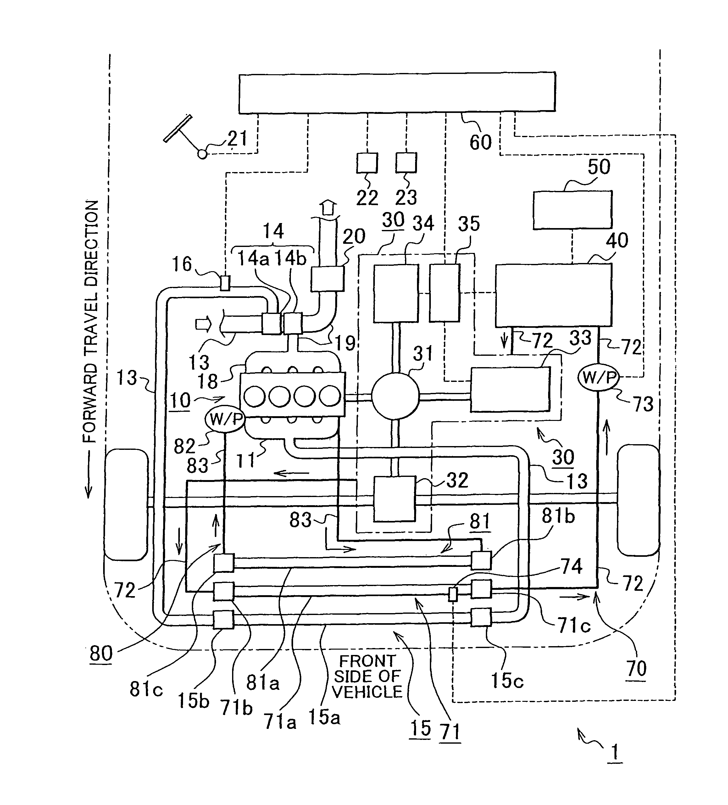
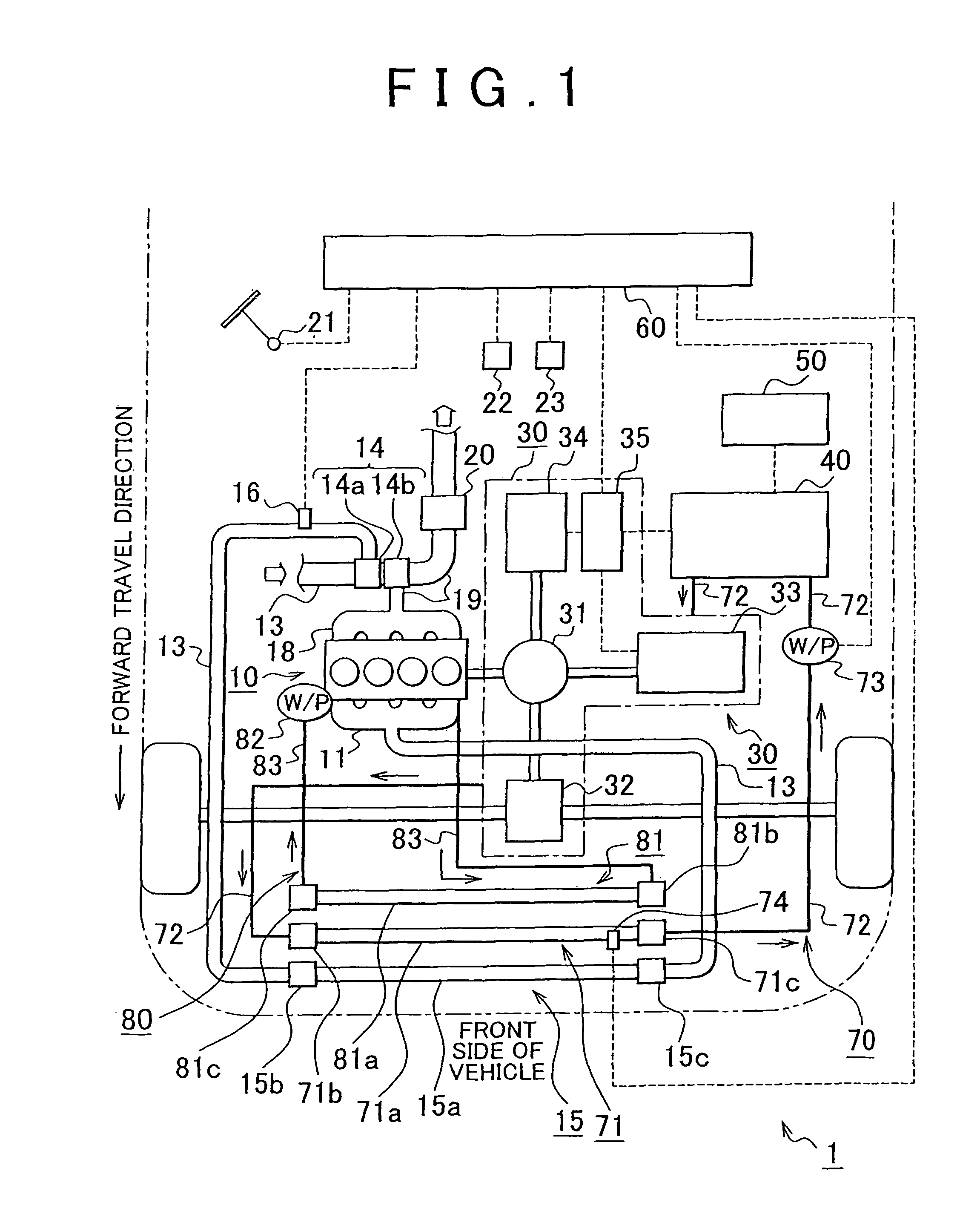
[0035]FIG. 1 is a diagram illustrating a schematic construction of a hybrid system 1 according to the present invention. As shown in FIG. 1, the hybrid system 1 is provided with an engine 10, a transaxle 30, an inverter 40, a battery 50, and a hybrid control unit 60 (hereinafter, referred to as “HV_ECU (Electronic Control Unit)”) that controls the entire hybrid system 1. In the drawings, a part of the outline (contour) of a hybrid vehicle is shown by a two-dot chain line.

[0036]The engine 10 generates a driving force (engine output power) of the hybrid vehicle from the fuel combustion energy as a source. The transaxle 30 is formed by a transmission and an axle integrated with each other. A power split device (for example, a planetary gear mechanism) 31, a reduction device 32, an electric motor 33, a generator 34, and a power control unit 35 (hereinafter, referred to as “MG_ECU”) that controls the electric motor 33 and the generator 34 are accommodated in the interior of the transaxle...

second embodiment

[0096]Further, according to the hybrid system 3, similar to the hybrid system 2 of the second embodiment, the ambient air introduced into the engine compartment flows smoothly. Therefore, the intercooler 15, the electric motor cooling system radiator 71 and the engine cooling system radiator 81 efficiently exchange heat with the ambient air. For example, the cooling efficient of the intercooler 15 to cool the boost air is further improved. In addition, because the electric motor cooling system radiator 71 and the engine cooling system radiator 81 are formed integrally, the materials to form them can be the same or in common, and the cost is reduced.

[0097]In the first to third embodiments described above, the intercooler 15 is disposed at the most front of the hybrid vehicle; however, the invention is not limited thereto. For example, an air conditioning condenser of an air conditioner that controls the passenger compartment temperature of the hybrid vehicle may be disposed further f...


PUM


Abstract

A hybrid system control apparatus is provided in which an intercooler is disposed upstream of the motor cooling radiator in a flow path of the ambient air flowing in an engine compartment, and / or is disposed such that at least a portion of the intercooler and a portion of the motor cooling radiator contact each other. The hybrid system control apparatus includes a warm-up portion that increases temperature of the boost air by controlling a load of the engine in cold start of a hybrid system such that the boost pressure from the forced air induction device is equal to or higher than a target boost pressure.

Description

BACKGROUND OF THE INVENTION[0001]1. Field of the Invention[0002]The present invention relates to a hybrid system control apparatus and a hybrid system control method.[0003]2. Description of the Related Art[0004]A hybrid system provided with an engine and an electric motor is known in which a hybrid vehicle is driven by a power produced by at least one of the engine and the electric motor. In the hybrid system, in addition to an engine system, an electric motor system, which is formed by, for example, an electric motor, a generator, an inverter, a transmission, or the like. Therefore, in the hybrid system, each of the systems may be provided with a cooling system that performs heat exchange with an exterior.[0005]Further, if the engine in the hybrid system has a forced air induction device, an intercooler that cools boost air (intake air) from the forced air induction device is usually provided. The forced air induction device increases the temperature of the boost air to, for exampl...

Claims


Application Information

Patent Timeline
Patent Type & Authority Patents(United States)
IPC IPC(8): B60L9/00G05D3/00G06F7/00G06F17/00G05D1/00B60L11/00B60K6/445B60K11/04B60K11/06B60L50/16B60W10/06B60W20/00F01P3/18F02B39/16F02D23/00
CPCB60K6/445B60W10/06B60W10/08B60W30/194F02B29/0425F02B29/0493B60K2001/003B60L2240/445B60W20/00B60W2510/0671B60W2510/0676B60W2520/10B60W2550/12F01P2037/02F01P2060/02F02B37/00F28D1/0435Y02T10/146Y02T10/6239Y02T10/6286B60Y2400/435B60W2555/20Y02T10/12Y02T10/62B60K6/08B60K11/06B60K11/04B60W20/15
Inventor MURATA, HIROKIMATSUMOTOMAGARIDA, NAOFUMIYAMASHITA, AKIRAHAGA, HIROYUKISAODA, TAKENORI
Owner TOYOTA JIDOSHA KK
Why Eureka
Try Eureka